

PP Fire-Resistant Closed-Check Valve
| Product Model | PPs soft-sealed fire-resistant check valve |
|---|---|
| Category | PP Machined Products |
| Reference Price | Price on request |
Product Overview
The PP Flame-Retardant Closed Check Valve is a self-actuated check valve with a soft seal made of flame-retardant PP material. It functions similarly to a standard PP closed check valve: allowing airflow in only one direction. During fan operation, the positive airflow lifts the valve disc; after shutdown, the disc closes under its own weight and reverse airflow. The soft seal presses against the valve seat to prevent backflow. The difference lies in the valve body, valve disc, and welding rods all being made of flame-retardant PP material, which self-extinguishes upon exposure to fire. It is suitable for corrosion-resistant exhaust systems in indoor, suspended ceiling, and fire-rated environments.
In laboratory, workshop, and pipe well applications, the check valve must be acid/alkali-resistant and flood-proof while maintaining consistent fire performance with the flame-retardant PP duct system. Standard PP check valves are flammable and can become a fire weak point in flame-retardant networks. The PPs Flame-Retardant Check Valve, when paired with flame-retardant ducts and dampers, ensures continuous flame-retardant material throughout the indoor corrosion-resistant exhaust system, meeting both fire and corrosion requirements for indoor corrosion-resistant ventilation projects.
The PP Flame-Retardant Closed Check Valve supplied by Xicheng Environmental Protection features molded or plate-welded PP valve bodies with single or multi-vane swing structures. The valve disc is equipped with a corrosion-resistant soft seal and a limit stop. The valve shaft is horizontally installed, and the valve is available in round, square, and various sizes, compatible with flame-retardant PP ducts. It is a dedicated valve for indoor corrosion-resistant fan outlets and parallel fan duct systems to automatically prevent backflow.
Working Principle
The backflow prevention mechanism of the flame-retardant check valve is self-actuated swing action. When the fan operates, the positive airflow differential pushes the valve disc, which swings around the horizontal valve shaft to a limited angle, allowing airflow. After shutdown, the positive pressure differential disappears, and the valve disc returns to its seated position under its own weight. If reverse airflow exists, the reverse pressure holds the valve disc against the seat, and the soft seal deforms under pressure to seal, preventing reverse airflow. The entire process requires no power or manual intervention and completes instantly upon shutdown.
The flame-retardant performance comes from the flame-retardant components in the PP material. The valve body, valve disc, and welding rods are difficult to sustain combustion upon exposure to open flames and self-extinguish, ensuring the check valve does not become a pathway for fire to spread through indoor ducts. Corrosion resistance maintains the chemical stability of polypropylene against acid, alkali, and salt exhaust gases, preventing rust or jamming of the valve disc and seat in corrosive environments. The soft seal is selected for its corrosion resistance and flame-retardant elasticity, preventing the seal from becoming a double weakness in flame-retardant and corrosion-resistant performance, ensuring long-term flexible operation and tight sealing of the valve disc.
Structural Composition
The flame-retardant closed check valve consists of a PP valve body, flame-retardant valve disc, valve shaft, valve seat, soft seal, limit stop, and end connections. The valve body is a molded cylindrical or plate-welded cylindrical shell with PP flame-retardant welding rods. The valve disc is a PP plate with a corrosion-resistant flame-retardant soft seal embedded at its edge, hinged to the valve body via a horizontal valve shaft for single-direction swing. A flat valve seat is installed at the fully closed position, and an limit stop is set on the opening side.
The valve shaft is made of corrosion-resistant metal or coated material, with a lightweight shaft sleeve at the shaft seat to ensure the valve disc can open with minimal differential pressure. Large-diameter valves use a multi-vane structure to reduce the size and weight of individual vanes, enhancing flexibility in opening and seating. The valve body ends are PP flanges or sockets for connection to flame-retardant ducts. Square check valves are used for rectangular ducts, with multiple vanes arranged in a grid pattern. The valve body is marked with airflow direction and installation orientation, and on-site installation should follow the markings.
Specification Model Table
The following table compares the flame-retardant check valve with a standard check valve for selection based on installation environment.
| Item | PPs Flame-Retardant Check Valve | Standard PP Check Valve |
|---|---|---|
| Flame-Retardancy | Self-Extinguishing | Non-Flame-Retardant |
| Corrosion Resistance | Acid/Alkali/Salt Resistant | Acid/Alkali/Salt Resistant |
| Applicability | Indoor Fire-Rated Environments | Outdoor Open Areas |
| Compatibility | Flame-Retardant PP Ducts | PP Ducts |
Product Features
The PP Flame-Retardant Closed Check Valve integrates flame-retardancy, corrosion resistance, and automatic backflow prevention, serving as a dedicated single-direction valve for indoor corrosion-resistant fan outlets. Key features include:
- Full flame-retardant PPs valve body, disc, and welding rods, self-extinguishing upon exposure to fire
- Self-opening in the forward direction and self-closing in reverse, requiring no power or operation
- Reverse self-tightening soft seal, minimizing leakage during closure
- Corrosion-resistant against acid, alkali, and salt, preventing rust or jamming of the valve disc
- Compatible with flame-retardant PP ducts for continuous fire performance
- Prevents backflow from indoor fans during shutdown and cross-flow in parallel ducts
- Available in single/multi-vane, round/square configurations, with customizable diameters
| Body Material | PPs Flame Retardant Boards |
|---|---|
| Welding Rod Material | PPs Flame-Retardant Welding Rod |
| Sealing Form | Corrosion-Resistant Flame-Retardant Soft Seal Ring |
| Action Method | Self-Acting Angle Type |
| Drive Energy | No power required |
| Valve disc type | Single-petal / Multi-petal |
| Flame Retardancy | Self-extinguishing |
| `Corrosion resistance performance` | Acid-alkali-resistant |
| Connection Method | `Spigot / Flange` |
| Installation Requirements | Shaft Horizontal |
Application Industries
- Anti-corrosion fan outlet flame-retardant check valve for laboratory indoor ventilation
- PPs exhaust fan anti-backflow valve for suspended ceilings and pipe shafts
- Anti-crossflow parallel fan in fireproof compartments of chemical workshops
- Anti-corrosion exhaust fan indoor check isolation valve for semiconductor plant
- Flame-retardant unidirectional valve for indoor fan outlet in electroplating workshops
- PPs exhaust shaft intake check valve for high-rise buildings
- Indoor corrosion-resistant fan automatic isolation valve with one primary and one backup
Typical Process Locations
The flame-retardant enclosed check valve is installed on the outlet or exhaust branch pipes of PPs flame-retardant fans in indoor, suspended ceiling, or fireproof compartments. The typical installation is one valve per indoor corrosion-resistant fan outlet. The valve flap opens during fan operation and closes automatically upon shutdown to prevent backflow from exhaust stacks and crossflow among multiple parallel fans. A check valve is also installed at the exhaust shaft intake point for floor exhaust to prevent crossflow between upper and lower floors. The valve connects to PPs flame-retardant ducts via flanges or spigot-and-socket joints, integrating into the entire flame-retardant corrosion-resistant duct system.
Installation requirements are the same as those for standard check valves: horizontal valve shaft, correct airflow direction marking, unobstructed valve flap rotation range, and brackets installed upstream and downstream of the valve. When passing through fireproof compartments, the check valve addresses backflow and material flame retardancy, but fire-rated fire dampers must still be installed separately per fire protection design and cannot be interchanged. Before commissioning, perform fan start/stop tests to observe the valve flap opening angle, return speed, and closing tightness. For variable frequency fans, check the stability of the valve flap at low speeds.
Related Products
View More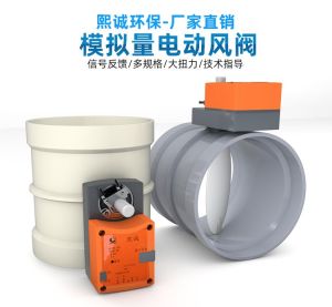 Hot
Hot
PP Fire-Resistant Analog Air Valve
 Hot
Hot
PP Flame Retardant Additive Drum
 Hot
Hot
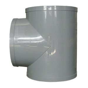
PP Flame Retardant Processed T-Connector
 Hot
Hot
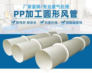
PP Fire-Retardant Process Ductwork
Get Quote
PP Fire-Retardant Process Ductwork / PPs soft-sealed fire-resistant check valve