
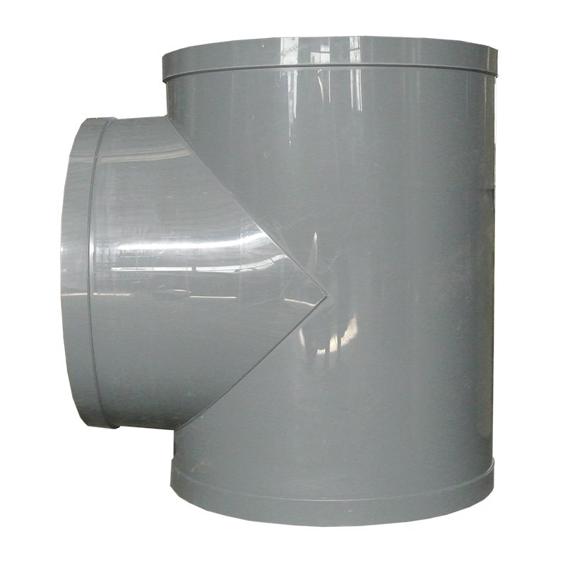
PP Flame Retardant Processed T-Connector
| Product Model | PPs plate welded branch tee |
|---|---|
| Category | PP Machined Products |
| Reference Price | Price on request |
Product Overview
The PP flame-retardant processing tee is a three-way connection component used in ventilation ducts when a branch pipe needs to be taken off from the main pipe. It is named for its three-directional interfaces. The tee can be made by cutting and welding PP flame-retardant plates or by processing formed parts. The three interfaces connect the inflow end, outflow end, and branch pipe of the main pipe, serving as a key component in the exhaust system for air flow diversion and convergence.
Tees are classified into equal-diameter and reducing types: equal-diameter tees have three interfaces of the same diameter, used for branching in pipes of the same diameter; reducing tees have the same main pipe diameter but a smaller branch pipe diameter, commonly used for diverting small branch pipes from large main pipes, which is the most common form in exhaust systems. Based on the branch pipe angle, they are further divided into straight tees and inclined tees. Inclined tees have the branch pipe angled along the airflow direction, resulting in lower resistance compared to the right-angle straight tees. Xicheng Environmental can process large specifications and various non-standard angles and diameters of flame-retardant tees.
The PP material makes the tee resistant to acid, alkali, and salt corrosion, self-extinguishing when exposed to fire, with welds and base material of the same material, ensuring continuous anti-corrosion and fireproofing at the branching position. Circular and rectangular systems are matched with round and square tees, respectively. Rectangular tees are formed by bending and welding plates, while circular tees can be welded from plates or assembled from formed parts.
Working Principle
Tees achieve pipe diversion and convergence. In an exhaust system, branch pipe airflow enters through a lateral interface and merges with the main pipe airflow to flow downstream together; in supply or distribution systems, the opposite occurs, with a portion of the main pipe airflow diverting into the branch pipe at the tee. Reducing tees maintain branch pipe velocity by reducing the branch pipe diameter, while inclined tees allow the branch pipe to enter at a sharp angle along the main pipe airflow direction, reducing the impact and eddies when the two airflow streams meet.
Tees are areas where local resistance and wear are more concentrated in pipelines. When airflow diverts or converges, the abrupt change in direction causes pressure loss, and dusty airflow can scour the diversion area. The smooth, corrosion-resistant, and wear-resistant surface of the PP material, combined with a reasonable inclined angle and transition radius, can reduce resistance and scouring. PP flame-retardant plates and matching welding electrodes ensure long-term use of the tee in corrosive gas and fireproofing environments, with continuous and sealed welds preventing air leakage at the branch point.
Structural Composition
Circular reducing tees consist of a main pipe shell and a branch pipe interface. The main pipe is a straight circular tube with an opening on the side for welding the branch pipe connection, with transition reinforcement added at the angle between the branch pipe and the main pipe, and flanges or sockets welded at the three ends. Inclined tees have the branch pipe inclined along the airflow direction, with the intersection line unfolded for smooth welding. Rectangular tees are formed by bending and welding plates into a main pipe and a branch pipe box, with optional internal flow guides.
Equal-diameter tees have three interfaces of the same size, while reducing tees have a smaller branch pipe interface that transitions through conical or inclined connections. Tee end connections include flanges, socket welding, and often include air valve interfaces on the branch pipe. Large-specification tees have reinforced plates or ribs welded to the outer wall and at the branch intersection points to withstand the weight of the branch pipe and airflow forces, with independent supports installed under the branch pipe during installation.
Specification Model Table
The following table categorizes the types of tees and their applicable scenarios, with pipe diameters matching the main and branch pipes.
| Category | Feature | Applicable |
|---|---|---|
| Equal-diameter tee | Three interfaces of the same diameter | Branching in same-diameter pipes |
| Reducing tee | Branch pipe diameter reduced | Diverting small branch pipes from large main pipes |
| Inclined tee | Sharp angle inclination | Reducing resistance |
Product Features
The PP flame-retardant processing tee is available in a full range of forms and can be produced in large specifications, serving as the core component for corrosion-resistant air duct branching and convergence. Key features include:
- PP flame-retardant plates welded, resistant to acid, alkali, and self-extinguishing
- Multiple forms available: equal-diameter, reducing, straight, and inclined
- Inclined tees align with airflow to reduce convergence resistance
- Customizable for large specifications and non-standard angles and diameters
- Reinforced welding at intersection points for robust structure
- Matching round and square tees for respective systems
- Flange and socket connections for easy integration with pipelines
| Material | PPs Flame Retardant Panels |
|---|---|
| Processing Technology | Plate Welding / Forming Combination |
| Interface Type | Equal Diameter / Variable Diameter |
| Branch angle | !-- Butt Splice / Angled Splice -- |
| Connection Method | Flange / Butt-welding |
| Flame Retardant Properties | Self-extinguishing |
| Corrosion resistance performance | Acid and Alkali Salt Resistance |
| Applicable Section | Round / Rectangular |
| Specifications and Features | Large-Scale Custom Non-Standard Manufacturing |
| Strengthening Method | Welded reinforcement at the junction |
| Flow Diversion Options | With guide flow structure |
Application Industries
- Branching nodes for exhaust main ducts to individual workshop branches
- Manifolds for multiple槽集气罩汇 into the main exhaust duct in electroplating production lines
- Tri-ways for exhaust from multiple fume hoods in laboratories to merge
- Splitter and merger fittings for waste gas network in chemical plant areas
- Layered connection tri-ways for exhaust shafts in semiconductor factory buildings
- Odor collection and merging points for multiple zones in wastewater treatment plants
- Rectangular ducts with flow guidance for high airflow split tri-ways
Typical Process Locations
The tri-way is installed at branching or merging points of main ducts. Branch ducts from various collection points in the exhaust system are connected to the main duct in a diverging elbow direction, merging progressively toward purification equipment and fans. The position and angle of branch duct connections to the main duct affect resistance balance. Design-wise, branch ducts should be angled斜接 from the side or top of the main duct at a sharp angle to avoid direct vertical collisions. Tri-way branch ducts are typically followed by manual dampers for adjusting airflow in each branch.
During installation, the main duct of the tri-way is axially aligned with the pipeline. The branch direction must comply with the drawings, with continuous and sealed longitudinal welds. Flange gaskets must be intact. The weight of the tri-way and branch ducts is supported by hangers, especially for large-diameter branch ducts, to prevent the tri-way welds from long-term cantilever loads. Diverging tri-ways have directional properties—the inclination must align with the main duct airflow. Incorrect installation will increase resistance. Before installation, verify the main and branch duct diameters, angles, and flange standards. For diverging tri-ways, the branch direction aligns with the main duct airflow, with continuous and full longitudinal welds for leakage inspection. The weight of branch ducts and valves is supported by hangers, ensuring the tri-way welds are not subjected to long-term cantilever loads. Temporary reinforcement of joints during hoisting, and重点 inspection of longitudinal welds and flange seals during operation. If leakage or deformation is detected, shut down and perform weld repairs.
Related Products
View More Hot
Hot
PP Fire-Resistant Analog Air Valve
 Hot
Hot
PP Fire-Resistant Closed-Check Valve
 Hot
Hot
PP Flame Retardant Additive Drum
 Hot
Hot
PP Fire-Retardant Process Ductwork
Get Quote
PP Fire-Retardant Process Ductwork / PPs plate welded branch tee