
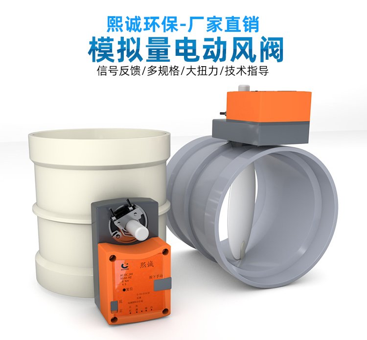
PP Fire-Resistant Analog Air Valve
| Product Model | PPs Analog Control Damper |
|---|---|
| Category | PP Machined Products |
| Reference Price | Price on request |
Product Overview
The PP Flame-Retardant Analog Damper is a PP flame-retardant damper equipped with an analog调节type electric actuator. Unlike switch-type electric dampers that can only open or close fully, it can receive continuous electrical signals from the control system, stabilizing the vane at any angle between fully closed and fully open, and feeding back the current position to the control system. This enables continuous, precise, and automatic regulation of airflow, making it the end-execution component for variable air volume (VAV) ventilation and intelligent exhaust systems.
In laboratory VAV fume hood systems, changes in the sash opening alter the exhaust area, requiring real-time airflow adjustment to maintain safe face velocity. In workshop negative pressure control, fan frequency modulation, and multi-circuit airflow balancing, dampers also need to operate continuously based on sensor signals. Analog dampers receive standard signals (commonly 0-10V voltage or 4-20mA current signals) from the controller. The servo circuit inside the actuator compares the target position with the actual position and drives the motor in forward or reverse direction, allowing the vane to precisely track the target opening.
The PP flame-retardant analog dampers supplied by Xicheng Environmental Protection are available in formed circular and plate-welded rectangular multi-leaf designs. The PP valve body is self-extinguishing and acid/alkali-resistant. The actuator is equipped with position feedback and a manual mechanism, and can interface with face velocity controllers, differential pressure sensors, PLCs, and building automation systems. It is suitable for corrosion-resistant exhaust systems in laboratories, chemical plants, and semiconductor facilities requiring precise ventilation control.
Working Principle
The core of an analog damper is position closed-loop control. The controller calculates the required damper opening based on the deviation between the setpoint (face velocity, differential pressure, or airflow) and the measured value, using a control algorithm, and outputs the corresponding analog signal. The actuator converts the signal into a target angle while internally measuring the actual angle of the output shaft using a potentiometer or encoder. When the two angles differ, the motor drives the vane through a reducer until the actual angle matches the target angle, achieving precise vane tracking.
Changes in vane angle alter the pipeline flow area and local resistance, thereby adjusting the branch airflow. In VAV fume hood systems, when the sash is opened wider, the controller commands the vane to open wider and increase exhaust airflow. When the sash is closed, the vane closes to reduce airflow, maintaining the face velocity at the sash opening within a safe range. This ensures pollutants are contained while avoiding unnecessary airflow waste. The PP valve body is corrosion-resistant and flame-retardant, with corrosion-resistant shaft seals and bushings ensuring smooth, non-sticking, and airtight operation of the vane in corrosive gases during long-term small-angle reciprocating adjustment.
Structural Components
Analog dampers consist of a PP valve body, vane (or multi-leaf vanes), shaft, shaft seat seal, analog regulating actuator, mounting bracket, and interfaces. The valve body is a formed cylinder or plate-welded rectangular frame, with the vane fixed to the shaft. Rectangular dampers use a multi-leaf联动 structure. The shaft's extending end connects to the analog actuator, which is mounted on the outside of the valve body via a bracket.
除了电机和减速机构外,模拟量执行器内部还包含位置检测元件、伺服控制电路板和反馈电路,具有控制信号输入和阀位信号输出端子,常见信号为 0-10V 或 4-20mA,部分型号支持总线通信。执行器带手动释放机构和开度刻度,调试和断电时可手动操作。阀体两端采用承插或法兰连接,阀瓣边缘可加装密封条以提高小开度时的调节线性度和关闭气密性。
Specification Model Table
The following table compares the functions of analog dampers and switch-type electric dampers. Signal standards must be specified during selection.
| Item | Analog Regulation Type | Switch Type |
|---|---|---|
| Position | Any opening degree | Full open/full close |
| Input Signal | 0-10V / 4-20mA | Switching signal |
| Position Feedback | Continuous feedback | End-of-travel contacts |
| Application | VAV negative pressure control | Start/stop interlock isolation |
Product Features
The PP flame-retardant analog damper can continuously and precisely adjust airflow with closed-loop feedback, making it the core valve for VAV and intelligent corrosion-resistant exhaust systems. Key features include:
- PP flame-retardant valve body, self-extinguishing and acid/alkali-resistant
- Receives standard analog signals, enabling continuous vane adjustment at any opening degree
- Internal position closed-loop for precise positioning and position feedback
- Automatically maintains face velocity and negative pressure stability with sensors
- Available in circular and rectangular multi-leaf designs, compatible with VAV
- Actuator with manual mechanism for operation during commissioning or power outages
- Reduces unnecessary exhaust, lowering fan and air conditioning energy consumption
| Body Material | Flame Retardant Polypropylene (PPs) |
|---|---|
| Body Type | Formed Round / Plate-welded Rectangular |
| Drive Type | Analog Electric Actuator |
| Control Signal | 0-10V / 4-20mA |
| Valve Position Feedback | Analog continuous feedback |
| Adjustment Characteristics | Continuous regulation at any opening |
| Flame Retardancy | Self-extinguishing |
| Corrosion resistance performance | Acid and Alkali Salt Resistant |
| Manual operation | Actuator with manual mechanism |
| System Integration | Controllers / PLCs / Building Automation |
Application Industries
- Lab VAV fume hood face velocity control
- Chemical lab exhaust main duct pressure differential VFD linkage adjustment
- Biosafety lab room negative pressure gradient control
- Semiconductor plant exhaust branch duct airflow automatic balancing
- Chemical workshop localized exhaust adjustment based on pollutant concentration
- VFD system terminal analog valve actuation
- Corrosion-resistant exhaust volume regulating valve for BMS integration
Typical Process Locations
Analog dampers are installed on PP corrosion-resistant ducts requiring continuous airflow control, most commonly at the exhaust ports of VAV fume hoods or on top of the cabinets. The valve actuator connects to the fume hood face velocity controller, with cabinet door displacement or face velocity sensor signals input to the controller. The controller outputs an analog signal to drive the dampers. On room exhaust branch ducts, analog valves work with room pressure differential or airflow sensors and VFD fans to form a closed loop, maintaining stable exhaust volume and negative pressure.
When integrating with BMS systems, ensure unified signal standards and ranges. Control signals and valve position feedback should use shielded cables with proper grounding to avoid interference from power cables causing vane vibration. During commissioning, first calibrate the vane's full open/close positions against signals, then perform closed-loop tuning with the controller. Verify the vane's followability and stability to signals, confirm face velocity remains within design specifications across different cabinet door openings, and finally document the valve position vs. airflow relationship curve.
Related Products
View More Hot
Hot
PP Fire-Resistant Closed-Check Valve
 Hot
Hot
PP Flame Retardant Additive Drum
 Hot
Hot
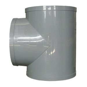
PP Flame Retardant Processed T-Connector
 Hot
Hot
PP Fire-Retardant Process Ductwork
Get Quote
PP Fire-Retardant Process Ductwork / PPs Analog Control Damper