
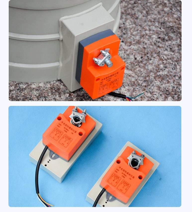
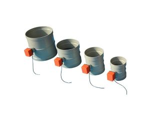
Switching Type Corrosion-Resistant Actuator
| Product Model | Corrosion-resistant switch actuator for air dampers |
|---|---|
| Category | Laboratory Products |
| Reference Price | Price on request |
Product Overview
The switch-type corrosion-resistant actuator is a dedicated electric device designed to drive corrosion-resistant dampers for two-position (full open/close) actions, specializing in on/off control within corrosion-resistant actuators. Upon receiving a switch signal, the motor drives the damper shaft from full close to full open or in reverse via a reduction mechanism. Once in position, it automatically powers off and holds, while also outputting a switch position signal. The product features corrosion protection for acid/alkali environments, offering anti-corrosion, high torque, long service life, rapid start/stop, and simple installation/maintenance. It is compatible with PP and PPs corrosion-resistant dampers.
In corrosion-resistant ventilation systems, many dampers only require two states: the damper opens when the equipment is running and closes during shutdown. Fan interlocking, branch line switching, and maintenance isolation all fall under this two-position control, eliminating the need for intermediate positions. The switch-type actuator has a simpler structure than the regulating type, offers convenient control, is cost-effective, and provides rapid and reliable operation, making it the standard configuration for follower dampers and interlocked dampers. Analog actuator is selected only when continuous damper adjustment is required for airflow control, with both types having clearly defined roles.
The switch-type corrosion-resistant actuators supplied by Xicheng Environmental Protection feature corrosion-resistant housings, sealed wiring, and corrosion-resistant shaft systems, with torque ranging from small to large, forming a series. They can be matched with circular and square corrosion-resistant dampers of various sizes, with a typical power supply of 220V. Equipped with full open/close position feedback and a manual operation mechanism, they can be interlocked with fans, production equipment, and control panels, widely used in laboratory, chemical, electroplating, and semiconductor corrosion ventilation systems for automatic damper operation.
Working Principle
The switch-type actuator adopts two-position control. When the control system provides an open damper signal, the motor powers on and rotates clockwise, driving the valve shaft through a worm gear and wheel or gear reduction mechanism. The valve vane rotates from the full close position to the full open position. When the full open position is reached, an internal limit switch activates to cut power, stopping the motor and holding the position, while simultaneously closing the open position contact to feedback the status to the control panel. For the close damper signal, the motor rotates counterclockwise, returning the valve vane to the full close position, activating the close position contact. A single power-on completes the full range of motion in one direction, hence the name two-position or on/off actuator.
Fast start/stop is a key feature of the switch-type actuator. The motor quickly starts upon receiving a signal and stops immediately upon reaching position, resulting in short full open/close travel times, meeting the timing requirements for equipment interlocking and emergency actions. Corrosion resistance is achieved through a corrosion-resistant housing, sealed wiring box, corrosion-resistant output shaft, and fasteners, preventing corrosive gases and salt spray from penetrating the motor and control components. Sealing at the valve shaft connection prevents gas leakage from the pipeline. The reduction mechanism features self-locking properties, ensuring the valve remains in position unaffected by airflow fluctuations, guaranteeing stable and reliable switching.
Structural Components
The switch-type corrosion-resistant actuator consists of a corrosion-resistant housing, motor, reduction mechanism, output shaft clamp, full open/close limit switches, position feedback contacts, manual operation mechanism, and sealed wiring box. The motor and reduction mechanism are enclosed within the corrosion-resistant housing, with the output shaft extending from the housing and secured to the damper shaft via a clamp. A bracket fixes the actuator to the damper body.
The wiring box includes power terminals, open/close control terminals, and full open/close feedback terminals, with the lid and cable inlet sealed for protection. An external manual operation button or handle allows manual valve operation during power failure or commissioning by disengaging the motor. Some models feature position indicators to display the current open/close status. Different torque specifications correspond to different damper sizes: small torque, fast-type actuators are used for small-diameter dampers, while large torque actuators are used for large-diameter and multi-leaf dampers. The output shaft clamp and bracket are matched to the damper shaft dimensions.
Specification Model Table
The following table compares the switch-type and regulating-type corrosion-resistant actuators for selection based on control requirements.
| Item | Switch-Type | Regulating-Type |
|---|---|---|
| Position | Full Open / Full Close | Any Angle |
| Input | Switch Signal | Analog Signal |
| Purpose | Interlocking and Isolation | Continuous Airflow Adjustment |
| Features | Fast Start/Stop, Cost-Effective | Precise Positioning |
Product Features
The switch-type corrosion-resistant actuator offers two-position operation, fast and reliable performance, and corrosion resistance, serving as a dedicated drive device for corrosion environment damper interlocking and operation. Key features include:
- Corrosion-resistant housing and sealed wiring, resistant to acid, alkali, and salt spray
- High torque reduction output, powerful for driving large-diameter dampers
- Fast start/stop, short full open/close travel, timely interlocking
- Position limit and feedback, switch status monitorable
- Reduction self-locking, valve remains in position unaffected by airflow
- Manual operation mechanism, allows manual switching during power failure or commissioning
- Mature structure for long service life, simple installation, wiring, and maintenance
| Type | Two-Position Switch |
|---|---|
| Typical Power Supply | 220V |
| Output Stroke | 0 to 90 degrees open and close |
| Function Features | Fast Start/Stop |
| Torque Specifications | Multi-speed high-torque series |
| Companion Port Size | Small Diameter to Large Diameter Air Valves |
| Anti-corrosion method | Corrosion-resistant enclosure with sealing |
| On-site feedback | Fully Open/Fully Closed Contacts |
| Self-locking Performance | Self-locking reduction mechanism |
| Manual operation | With manual mechanism |
Application Industries
- Lab fume hood exhaust dampers open/close with fume hood power supply
- Electroplating line side dampers link with production line operation
- Chemical equipment exhaust dampers with remote corrosion-resistant control
- Multiple fan parallel branch valves with interlocked on/off operation
- Semiconductor wet etch equipment exhaust dampers with equipment interlock
- Corrosion-resistant exhaust system maintenance isolation electric switch valves
- Emergency ventilation system signal-actuated rapid opening dampers
Typical Process Locations
The switching-type corrosion-resistant actuator is installed on corrosion-resistant dampers requiring full open/close operation, most commonly on exhaust branch valves for production equipment and fume hoods: when equipment starts, the actuator opens the damper, allowing fans or equipment to operate after reaching full position; when equipment stops, the actuator closes the damper to prevent short-circuit suction and gas backflow in inactive branches. When multiple equipment share a fan, each branch switching damper operates in coordination with the equipment's operational status. The actuator connects to PLC or control cabinet switch output and input points, performing sequential interlock with the fan.
During installation, the actuator bracket must be securely fixed, the output shaft aligned coaxially with the valve shaft, the clamping plate tightened, the wiring box inlet sealed, and the manual mechanism oriented for ease of operation. Commissioning begins with manual rotation to confirm full-range damper operation without binding, followed by on-site electric verification of switching direction, travel time, and position signals, and finally system interlock testing: verifying the logic of starting the fan only after the damper fully opens, closing the damper after shutdown, and rapid valve action under emergency signals. Regularly perform full-range switching tests during operation to inspect limits, feedback, and corrosion-resistant condition of the shaft system.
Related Products
View More
 Hot
Hot
Venturi Valve
 Hot
Hot
Ventilation Hood
 Hot
Hot
Corrosion-resistant actuator
Get Quote
Corrosion-resistant actuator / Corrosion-resistant switch actuator for air dampers