
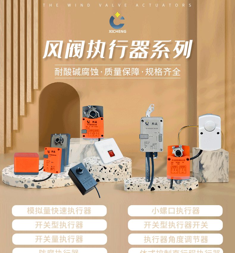
Actuator
| Product Model | Electric Air Valve Angle Actuator Series |
|---|---|
| Category | Laboratory Products |
| Reference Price | Price on request |
Product Overview
The damper actuator is an electric device installed on the damper shaft to provide power for the vane rotation, also known as an angle actuator or damper actuator. It receives electrical signals from the control system, and the internal motor converts high-speed low-torque rotation into low-speed high-torque output through a reduction mechanism, driving the damper shaft to rotate within a 0 to 90-degree range, thereby actuating the vane to open or close. The operation of electric dampers, electric tight shut-off dampers, and variable air volume (VAV) dampers is all completed by the actuator, making it the end actuation component of automatic control in ventilation systems.
Actuators are classified into on-off type and regulating type based on control methods: the on-off type moves to fully open or fully closed positions upon receiving a power signal, used for remote actuation and interlocking of dampers; the regulating type (analog type) receives standard analog signals and can stop at any angle, used for continuous air volume adjustment. Actuators generally include mechanical limit switches, position feedback, manual operation levers, and overload protection. Some models are equipped with spring return, automatically returning to fully open or fully closed safety positions when power is lost. The key to selection is matching the output torque with the required torque of the damper and ensuring a safety margin.
Xichen Environmental supplies various torque and control method actuators, compatible with circular, square, and manual-to-electric PP dampers. They are also suitable for VAV dampers in ventilation cabinets and laboratory ventilation systems. Standard models are used in normal environments, corrosion-resistant actuators are selected for corrosive gas environments, on-off types are used for interlocking and isolation, and analog types are used for VAV adjustment. Voltage, torque, and signal formats are configured according to control system requirements.
Working Principle
The basic principle of the actuator is motor reduction drive and position control. Upon power activation, the motor rotates, and the speed is reduced and torque is amplified through gear or worm gear reduction mechanisms. The output shaft is rigidly connected to the damper shaft via a clamp or coupling. When the output shaft rotates, it drives the vane to rotate synchronously. On-off actuators operate until the internal cam triggers a limit position, then power is cut to stop, achieving full open or full closed operation. For reverse action, the power phase sequence is switched or another coil is energized.
Regulating actuators have position detection and servo circuit boards internally. The input signal corresponds to the target angle, and a potentiometer or sensor detects the actual output shaft angle. When the actual angle does not match the target angle, the motor rotates forward or backward until the actual angle equals the target angle, and outputs a valve position feedback signal, allowing stable stopping at any position. Spring-return types compress or stretch a spring while the motor is energized to maintain the working position, and the spring releases to pull the shaft back to a preset safety position when power is lost. The output torque of the actuator must overcome the aerodynamic torque of the vane, friction at the shaft seat, and sealing pressure. Insufficient torque can cause valve movement issues or motor overload.
Structural Composition
The actuator consists of a motor, reduction mechanism, output shaft clamp, limit mechanism, control circuit board, housing, and manual operation mechanism. The motor is the power source of the actuator, and the reduction mechanism typically uses worm gears or gear sets to reduce motor high-speed rotation to low-speed output shaft rotation while amplifying torque. The output shaft clamp directly engages the square or circular damper shaft, with some models using linkages for drive.
The housing has mechanical limit switches and travel switches at both ends or one side to limit the 0 to 90-degree travel. The regulating type housing includes a servo board, signal terminals, and position feedback components. The housing protection level adapts to the installation environment, and the housing is equipped with a manual operation lever or handle, allowing manual rotation of the shaft for commissioning or when power is lost. The wiring includes power supply, control signals, feedback signals, and ground terminals. Spring-return types incorporate a return spring and clutch mechanism internally. Actuators are mounted on the damper body or ductwork via mounting brackets, with the output shaft coaxially connected to the valve shaft.
Specification Model Table
The following table lists the main classifications and applications of actuators. Selection should be based on the damper torque and control requirements.
| Classification | Operation Characteristics | Typical Applications |
|---|---|---|
| On-off Type | Full Open/Full Closed | Isolation and Interlocking |
| Regulating Type | Any Angle | Continuous Air Volume Adjustment |
| Spring-Return Type | Power Loss Returns to Safety Position | Safety Interlocking |
Product Features
Actuators offer a full range of torque specifications and diverse control methods, serving as standard power components for electric dampers and ventilation automation. Key features include:
- Motor reduction drive ensures stable output torque and reliable operation
- Covers both on-off and analog regulation types
- 0 to 90-degree travel with accurate limit switches and position feedback
- Direct clamp connection to valve shaft, compatible with various dampers
- Manual operation mechanism allows manual switching during commissioning or power loss
- Spring-return types automatically return to safety position upon power loss
- Various torque, voltage, and protection levels with complete matching options
| Power Form | Electric Motor |
|---|---|
| Output Stroke | Rotation from 0 to 90 degrees |
| Reduction Gearbox | Gears / Worm Gears |
| Control Type | Switching / Regulating |
| Signal Adjustment | Standard Analog Input Available |
| Position Feedback | Limit Switch / Valve Position Feedback |
| Manual operation | With manual mechanism |
| Reset Options | Spring Return Optional |
| Connection Method | Clamping Plate Directly Connected Valve Shaft |
| Core Selection | Torque Matching with Safety Margin |
Application Industries
- Motorized dampers and VAV actuators for laboratory fume hoods
- Remote on/off actuation for corrosion-resistant exhaust systems
- Motorized closure and spring-return actuators for sealed valves
- Actuation mechanisms for fresh air and air conditioning systems
- Motorized actuators for fan inlet/outlet interlock dampers
- End damper actuators for building automation ventilation systems
- Power upgrades for converting manual dampers to motorized ones
Typical Installation Locations
The actuator is directly mounted on the outside of the damper body, with the output shaft flange connected to the damper shaft. The actuator bracket is fixed to the damper body. Switch-type actuators are used for exhaust branch duct motorized dampers, fan interlock dampers, and sealed isolation dampers, connected to relay outputs in the control cabinet. Adjustment-type actuators are used for VAV Venturi dampers and analog dampers, connected to controller analog signals. Installation locations should allow for observation of actuator scales and manual operation, avoiding dripping from the damper body, high temperatures, and direct spray of strong corrosion. For outdoor or humid environments, select the appropriate protection level.
During installation, first verify that the actuator power voltage matches the nameplate. Ensure the output shaft is coaxial with the valve shaft and the flange is tightened. The fully open/close position of the valve plate should correspond to the actuator travel. Wiring should be performed by electricians according to the diagram, with signal wires and power wires separated. The commissioning sequence is: first, manually turn the actuator to confirm full-range flexibility of the damper, then locally power on to verify switch direction and limits, and finally connect to the system for remote and interlock coordination. During operation, regularly inspect the actuation flexibility, bracket tightness, and sealing protection. For valves that are inactive for extended periods, periodically energize them for operation.
Related Products
View More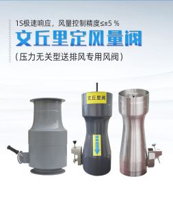 Hot
Hot
Venturi Valve
 Hot
Hot
Ventilation Hood
 Hot
Hot
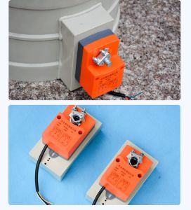
Switching Type Corrosion-Resistant Actuator
 Hot
Hot
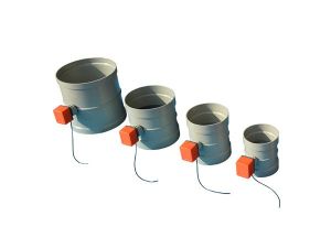
Corrosion-resistant actuator
Get Quote
Corrosion-resistant actuator / Electric Air Valve Angle Actuator Series