
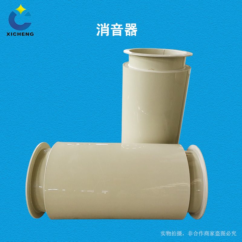
Circular Ventilation Duct Silencer
| Product Model | Cylindrical Resistive / Impedance Composite Muffler |
|---|---|
| Category | PP Machined Products |
| Reference Price | Price on request |
Product Overview
The round duct muffler is a cylindrical noise-reducing device installed at the outlet of circular corrosion-resistant ducts, fan outlets, and before exhaust stacks. The outer casing is made of flame-retardant PPs sheet material, rolled and welded. The inner wall is lined with a ring-shaped sound-absorbing layer or an internal sound-absorbing tube is installed inside the cylinder. When airflow passes through the internal passage of the cylinder, the sound energy is absorbed by the sound-absorbing material, thereby reducing the fan noise transmitted along the circular duct and radiated to the exhaust stack outlet.
Fan noise contains different frequency components: The resistive muffling section utilizes porous sound-absorbing materials to effectively reduce mid-to-high frequency noise; the reactive muffling section uses expansion chambers and resonance chambers formed by abrupt changes in the duct cross-section, causing specific frequency sound waves to reflect and interfere within the chambers, leading to attenuation, which is effective against low-to-mid frequency noise and pulsating noise. Round mufflers can be designed as resistive single cylinders or as impedance composite types by combining resistive and reactive sections to achieve noise reduction over a wider frequency range, making them a common solution for noise control in round exhaust systems.
Xicheng Environmental can design and manufacture round duct mufflers based on fan airflow, noise frequency spectrum, circular duct, and exhaust stack diameter, determining the cylinder diameter, thickness of the sound-absorbing layer, perforation rate of the internal tube, and muffling length. The round flanges are matched with ducts, and can also be combined with fan outlet reducers and flexible connections to form complete fan exhaust systems, suitable for noise reduction at fan outlets and exhaust stacks in corrosion-resistant ventilation systems.
Working Principle
The principle of the resistive section is sound energy dissipation: the central airflow passage consists of a perforated internal tube, with a ring-shaped space filled with sound-absorbing material outside the tube. Sound waves pass through the perforations into the sound-absorbing layer, causing the air inside the material's pores to vibrate. Due to friction and viscosity, sound energy is converted into thermal energy and dissipated. Mid-to-high frequency sound waves have shorter wavelengths and are easily absorbed into the pores, resulting in significant attenuation. The airflow passage remains unobstructed, and the sound-absorbing material is fixed by a perforated protective tube and protective fabric to prevent it from being carried away by the airflow.
The principle of the reactive section is sound reflection and interference: when the duct is connected to an expansion chamber or resonance chamber with a larger cross-sectional area than the fan duct, sound waves reflect at the abrupt change in cross-section, with some sound energy returning toward the sound source. When the chamber dimensions match specific wavelength sound waves, resonance occurs, canceling out that frequency of noise, leading to attenuation. Reactive sections do not require sound-absorbing materials and are effective against low-frequency and pulsating noise, and they are not affected by oil, moisture, or humidity. By connecting the resistive and reactive sections in series to form an impedance composite muffler, it can cover high, mid, and low frequencies. The PPs outer casing is corrosion-resistant and flame-retardant, ensuring long-term effective noise reduction in corrosive gas environments.
Structural Composition
The round muffler consists of a cylindrical outer casing, an internal sound-absorbing tube (or sound-absorbing plates), sound-absorbing material, a protective structure, reactive chambers, and two end flanges. The resistive section's outer casing is a PPs rolled cylindrical tube, with a perforated PPs internal tube at the center. The annular space between the internal tube and the outer casing is filled with sound-absorbing cotton, and the inner wall of the perforated tube can be lined with a protective fabric to prevent fiber leakage and liquid droplet entry.
In the impedance composite type, an expansion chamber is connected in series at the front or rear of the resistive cylinder. The expansion chamber is a sealed cylindrical tube with an increased diameter. Internally, it is equipped with insert tubes and baffle plates as per acoustic design to form reactive muffling units. Circular flanges are welded at both ends to connect with the ducts and exhaust stacks. Reinforcing rings are installed on the outer wall of the cylinder according to negative pressure and length, and a liquid discharge port is provided at the bottom if necessary to prevent liquid accumulation. Large-diameter mufflers can have an acoustic cone added at the center or be modified into multi-channel designs to increase the effective sound-absorbing perimeter.
Specification Model Table
The following table shows the types and applicable frequency bands of round mufflers, selected based on the fan noise frequency spectrum.
| Form | Noise Reduction Principle | Main Effective Frequency Band |
|---|---|---|
| Resistive Cylinder | Porous Sound Absorption | Mid-to-High Frequency |
| Reactive Expansion Chamber | Reflection and Interference | Low-to-Mid Frequency Pulsating |
| Impedance Composite | Series of Both | Wideband |
Product Features
The round duct muffler has good pressure-bearing capacity and combinable frequency bands, making it a common device for noise reduction in circular corrosion-resistant fans and exhaust stacks. Its main features are as follows.
- The cylindrical outer casing has uniform stress distribution, suitable for fan outlet pressure-bearing
- The resistive section effectively reduces mid-to-high frequency fan noise
- The reactive section targets low-to-mid frequency and pulsating noise, and is not affected by moisture
- The impedance composite type provides wideband noise reduction, suitable for complex noise frequency spectra
- PPs outer casing and perforated internal tube are acid-base resistant and self-extinguishing
- Round flanges are matched with circular ducts and exhaust stacks, offering low resistance
- Cylinder diameter and length are designed based on airflow and noise, and can be supplied as complete sets
| Outer casing material | PPs Flammability Retardant Panels |
|---|---|
| Section Shape | Round |
| Quietening Form | Resistance / Impedance Composite |
| Sound Absorbing Structure | Perforated inner pipe with annular acoustic layer |
| Resistance structure | Expansion Chamber / Resonant Chamber Optional |
| Connection Method | Round Flange |
| Effective Bandwidth | Broadband Impedance Composite |
| Corrosion resistance performance | Acid and Alkali Salt Resistant |
| Flame Retardancy | Self-extinguishing |
| Specifications Design | Based on airflow noise design |
| Installation Location | Exhaust stack in front of the fan outlet |
Application Industries
- Anti-corrosion centrifugal fan outlet duct muffling and noise reduction
- Exhaust muffler at the front of exhaust stack in waste gas treatment system
- Impedance composite muffler for factory boundary noise control
- Round exhaust silencer for laboratory rooftop exhaust fan
- Noise reduction for outdoor anti-corrosion fan in chemical plating workshop
- Low-frequency muffling for prominent fan pulsation noise
- Matching muffling section for round exhaust shaft and exhaust stack
Typical Process Locations
Round mufflers are typically installed between the fan outlet and exhaust stack. The fan outlet connects to the muffler via flexible joints and reducer pipes, then discharges into the exhaust stack, attenuating fan noise before it radiates from the stack outlet. When the fan inlet draws air from outdoors or a workshop, a muffler can also be installed at the inlet to reduce noise transmission. For factory boundary noise compliance, mufflers should be placed as close as possible to the exhaust stack outlet or directly as the base muffling section of the stack to minimize regenerated noise from downstream piping.
During installation, flexible joints must be used between the muffler and fan to isolate vibration, preventing fan vibration from transmitting to the thin-walled silencer and causing solid-borne sound transmission and shell booming. Round flanges should be aligned and tightened with gaskets sealed. The weight of the muffler and exhaust stack is supported by independent brackets to avoid pressure on the fan. The internal airflow velocity must be controlled within the recommended range, as high-speed airflow can generate regenerated noise, rendering muffling ineffective. After commissioning, regularly inspect the liquid drain, perforated inner pipe, and acoustic absorption layers. Remove fog from mist-containing gases first to prevent the absorption material from caking due to moisture.
Related Products
View More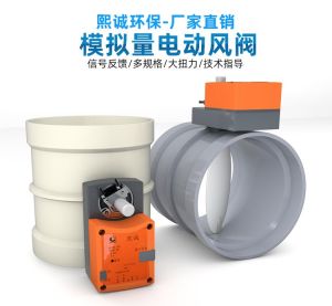 Hot
Hot
PP Fire-Resistant Analog Air Valve
 Hot
Hot
PP Fire-Resistant Closed-Check Valve
 Hot
Hot
PP Flame Retardant Additive Drum
 Hot
Hot
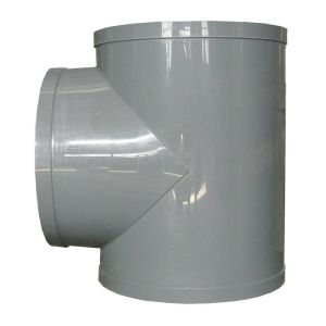
PP Flame Retardant Processed T-Connector
Get Quote
PP Flame Retardant Processed T-Connector / Cylindrical Resistive / Impedance Composite Muffler