
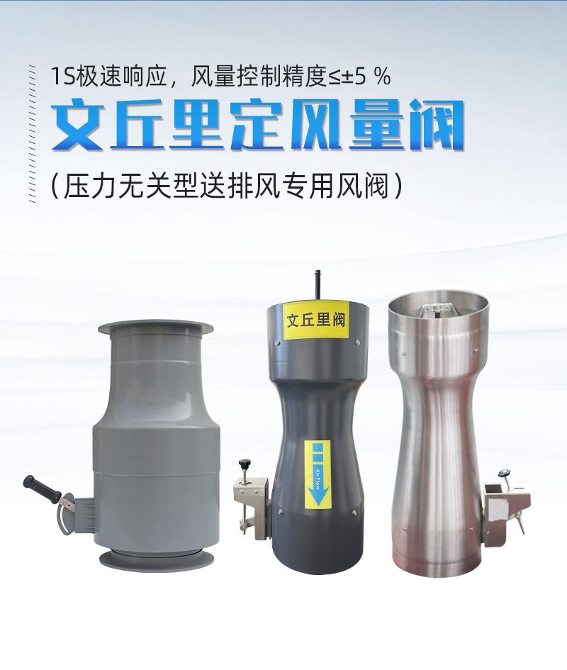
Venturi Valve
| Product Model | Venturi Constant Air Volume Valve (CAV) |
|---|---|
| Category | Laboratory Products |
| Reference Price | Price on request |
Product Overview
The Venturi Variable Air Volume (VAV) Damper, also known as the Venturi Constant Airflow Damper, is a specialized valve used in laboratory ventilation systems to automatically maintain a constant exhaust airflow. It is commonly referred to as a CAV Damper. The valve has a Venturi tube-like appearance and is equipped with an axially movable conical valve core and a spring adjustment mechanism, installed on the exhaust branch pipe of a fume hood. When the system pressure fluctuates due to other ventilation柜 openings, variable frequency fans, or clogged filters, the valve core automatically moves under the action of pressure difference and spring force to change the flow area, ensuring the airflow through the valve remains at the set value without requiring power or control signals.
With conventional dampers, once the opening is fixed, the airflow changes with network pressure variations. In multi-fume hood parallel systems, opening or closing certain units can cause airflow fluctuations in others, making it difficult to maintain consistent face velocity. Venturi Dampers rely on mechanical self-regulation to lock the exhaust airflow of each fume hood at the set value. After a one-time system airflow balancing adjustment, the system remains stable long-term, unaffected by other terminal openings, significantly enhancing fume hood safety and eliminating the need for frequent adjustments. The valve body is molded as a single unit, available in materials such as ABS, stainless steel, and aluminum alloy, with corrosion-resistant versions capable of withstanding acidic and alkaline gases.
The Venturi Constant Airflow Dampers supplied by Xicheng Environmental are molded as a single unit, compact in structure, corrosion-resistant, and acid/alkali-resistant. They feature an airflow setting mechanism on the valve for on-site setting based on the fume hood's designed exhaust airflow. The circular interface connects to ductwork and is suitable for constant airflow ventilation systems in chemical laboratories, testing institutions, and semiconductor manufacturing facilities. For applications requiring dynamic airflow adjustment with sash openings, Variable Air Volume Venturi Dampers should be selected.
Working Principle
The Venturi Damper achieves constant airflow using the Venturi throttling effect and force balance principles. The conical valve core forms a annular throttling passage between the valve core and the valve body. One side of the valve core is subjected to spring thrust, while the other side is affected by the aerodynamic force generated by the pressure difference between the valve front and rear. When the pressure difference increases, the aerodynamic force pushes the valve core to move in the direction of closing, reducing the annular passage area and increasing resistance, thereby counteracting the pressure rise. When the pressure difference decreases, the spring pushes the valve core to open, increasing the passage area. The valve core reaches a new position of force balance, maintaining the airflow through the valve relatively constant within a certain pressure difference range.
This regulation is entirely mechanical, achieved through the balance of the valve core and spring forces, eliminating the need for external power, sensors, or controllers, thus ensuring high reliability and fast response. It is classified as a self-powered constant airflow device. The Venturi-shaped flow channel in the valve body accelerates airflow and forms a stable pressure difference characteristic. The valve core position has a definite correspondence with airflow, and adjusting the setting mechanism changes the spring pre-tension to set different constant airflow values. The corrosion-resistant valve body and valve core do not rust or jam when long-term exposed to laboratory acidic and alkaline exhaust, ensuring smooth movement of the mechanical mechanism in corrosive environments.
Structural Components
The Venturi Damper consists of a valve body, conical valve core, valve core guide rod, spring assembly, airflow setting mechanism, and two end interfaces. The valve body is a Venturi-shaped cylinder, molded as a single unit with an inner wall profile designed according to the Venturi flow channel. The two circular interfaces connect to ductwork via slip-fit or flange connections. The conical valve core is located at the center of the valve body and moves axially along the guide rod, forming a annular airflow passage between the valve core and the valve body.
The rear of the valve core is connected to the spring and adjustment mechanism, where the spring force counteracts the aerodynamic force and maintains balance. The valve body exterior features airflow markings and a setting knob or locking mechanism. During commissioning, the valve is set to the designed exhaust airflow of the fume hood and locked. The valve may include a limit structure to restrict the valve core travel, ensuring effective regulation within the working pressure difference range. Corrosion-resistant valve bodies and valve cores are treated with ABS, stainless steel, or aluminum alloy for corrosion resistance. With few moving parts, maintenance is minimal. Installation direction follows valve body airflow indicators, with horizontal or vertical installation determined based on model requirements.
Specification and Model Table
The table below compares the Venturi Constant Airflow Damper with conventional dampers. Selection should be based on terminal control methods.
| Item | Venturi Constant Airflow Damper | Conventional Damper |
|---|---|---|
| Flow Control | Automatically constant under pressure difference fluctuations | Fixed opening, flow varies with pressure |
| Power Control | Power-free | Manual / Electric |
| Application | Constant airflow fume hoods | General airflow balancing |
| Commissioning | One-time setting, long-term stable | Affected by terminal openings |
Product Features
The Venturi Damper is mechanically self-powered, maintains constant airflow, and requires no power, making it a reliable terminal device for laboratory constant airflow ventilation systems. Key features include:
- Combines Venturi effect with spring force balance to maintain constant airflow under pressure difference fluctuations
- Pure mechanical self-regulation, no power, sensors, or controllers required
- One-time setting for long-term stability, unaffected by other terminal openings
- Molded valve body, compact structure, few moving parts
- ABS, stainless steel, or aluminum alloy material, corrosion-resistant, acid/alkali-resistant
- Includes airflow marking and setting mechanism for convenient on-site adjustment
- Fast response, reliable operation, low maintenance requirements
| Body Material | ABS / Stainless Steel / Aluminum Alloy |
|---|---|
| Molding Process | One-piece housing |
| Control Method | Mechanical Self-Adjusting Volume Control |
| Power Requirements | No power required |
| Measurement Principle | Venturi Throttling Effect |
| Adjustment Components | Conical Valve Core with Spring |
| Corrosion resistance performance | Anti-corrosion, Acid and Alkali Resistant |
| Setting Method | Body Scale Setting Lock |
| Connection method | Round Spigot / Flange |
| Applicable Systems | Variable Air Volume Fume Hood Exhaust |
Application Industries
- Chemical laboratory variable air volume fume hood exhaust control
- Examination institutions and third-party laboratory fume hood terminals
- Pharmaceutical companies QC laboratory variable air volume exhaust system
- Semiconductor and panel factories wet etching area variable air volume exhaust
- Schools and research institutions chemical laboratory fume hoods
- Variable air volume exhaust control for multiple fume hoods in parallel
- Hospital pathology and clinical laboratory variable air volume fume hoods
Typical Process Locations
The Venturi valve is installed on the exhaust branch pipe of each variable air volume fume hood, typically located between the cabinet top exhaust port and the horizontal main pipe or on the branch pipe before entering the vertical shaft. The valve body connects to circular ducts at both ends. Each fume hood is equipped with one variable air volume valve to lock the exhaust volume at the design value. The fume hoods are paralleled into the exhaust main pipe and centralized fan. When one hood is shut down, the branch pipe is closed, and the valves of the remaining hoods automatically adapt to pressure changes to maintain airflow. Sufficient space should be left for scale setting and maintenance, and airflow direction should be installed according to the valve body markings.
During system commissioning, the fan is turned on and the system operates under design conditions. Each Venturi valve is set to the fume hood's rated exhaust volume, and the window face velocity is verified using an anemometer or flow hood, then the setting mechanism is locked. Afterward, the system automatically maintains the airflow under various terminal switch combinations. Variable air volume Venturi valves are suitable for fume hoods with fixed or preset window openings. If constant face velocity is required at any window opening while achieving energy savings, variable air volume Venturi valves should be used.
Related Products
View More
 Hot
Hot
Ventilation Hood
 Hot
Hot
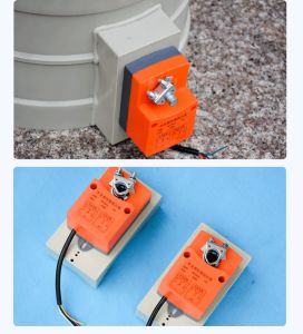
Switching Type Corrosion-Resistant Actuator
 Hot
Hot
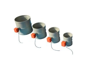
Corrosion-resistant actuator
Get Quote
Corrosion-resistant actuator / Venturi Constant Air Volume Valve (CAV)