
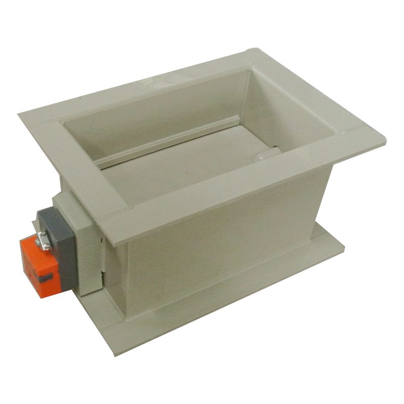
PP Processing Electric Square Air Valve
| Product Model | PP board welded rectangular electric multi-leaf valve |
|---|---|
| Category | PP Machined Products |
| Reference Price | Price on request |
Product Overview
The PP processed electric square damper is an automatic square air damper composed of an electric actuator assembled onto a rectangular valve body welded from PP boards, driving multiple valve leaves to operate in unison. Its valve body and multi-leaf linkage structure are identical to those of manual square dampers, with the difference being the use of an electric actuator instead of a handle. After the control system issues an electrical signal, the actuator drives the main valve shaft to rotate, which, through a crank-connecting rod mechanism, synchronizes the opening or closing of all valve leaves, achieving remote automatic start and stop of rectangular air ducts.
Rectangular air ducts are widely used in equipment interfaces, fume hood exhausts, and wall-mounted or ceiling-mounted exhaust branch pipes. When these areas require automatic start/stop with equipment, zoning control, or unattended operation, electric square dampers must be used. The damper is linked with fans and production equipment, automatically opening corresponding branch valves when equipment starts and closing them when it stops, preventing short-circuit suction in non-operating branches and ensuring effective exhaust volume. Ordinary PP valve bodies are acid and alkali resistant, making them suitable for rectangular exhaust applications with moderate corrosivity and no special flammability requirements.
Xicheng Environmental can process PP electric square dampers according to the cross-sectional dimensions of rectangular air ducts. The number of valve leaves is determined by the valve height, and they are equipped with switching or regulating type electric actuators with valve position feedback. The square flange is matched with rectangular air ducts. For indoor and suspended ceiling applications with flammability requirements, the same product made of flame-retardant PP material can be selected.
Working Principle
The electric square damper works by coordinating the electric actuator and the multi-leaf linkage mechanism. After receiving a switching electrical signal, the motor in the actuator drives the output shaft to rotate approximately 90 degrees. The output shaft is connected to the valve shaft of the main valve leaf. The crank at the end of the main valve shaft is driven by a vertical connecting rod to move the cranks at the ends of the other valve shafts, forming a parallel four-bar linkage mechanism, ensuring all valve leaves rotate at the same angle synchronously to open or close the rectangular cross-section.
The multi-leaf linkage evenly distributes the rotational motion of the actuator to multiple narrow valve leaves, with each valve leaf rotating only its small area of blade, resulting in low stress and good synchronization. After the actuator reaches its position, an internal limit stops it and outputs a switch position signal. The PP valve body and valve leaves are resistant to acid and alkali fume corrosion and do not rust; the linkage pins and bushings are made of corrosion-resistant materials to ensure smooth operation of the multi-leaf mechanism in corrosive environments. When the valve leaves close, their edges overlap, reducing air leakage, and a soft sealing strip can be added for airtightness.
Structural Composition
The electric square damper consists of a PP rectangular valve body, multiple valve leaves, valve shafts, crank-connecting rod linkage mechanism, electric actuator, actuator bracket, and square flange. The valve body is formed by folding and welding PP boards into a square frame and reinforced. The valve leaves are narrow, long PP board strips arranged parallel along the valve height, each fixed to the valve shaft, with both ends of the shaft supported on the side walls of the valve body.
Each valve shaft extends outward on the same side and is equipped with a crank, connected by connecting rods for synchronization. One end of the main valve shaft is connected to the electric actuator via a coupling, which is supported by a bracket fixed to the side of the valve body. The actuator contains a motor, reduction gears, limit switches, and feedback mechanisms and can be manually reset. The valve body has square PP flanges at both ends, and sealing strips can be embedded at the edges and ends of the valve leaves. For large cross-sectional area dampers, the actuator torque must overcome the total aerodynamic moment of multiple valve leaves, so a safety margin should be considered during selection.
Specification Model Table
The following table provides a comparison between electric square dampers and manual square dampers, with cross-sectional dimensions matched to rectangular air ducts.
| Item | Electric Square Damper | Manual Square Damper |
|---|---|---|
| Drive | Remote actuator | On-site handle |
| Control | Interlocked automatic | Manual adjustment |
| Application | Equipment linked branches | Fixed airflow balancing |
| Feedback | With valve position signal | None |
Product Features
The PP processed electric square damper features multi-leaf synchronization and remote interlocking, making it a common valve for automatic corrosion-resistant rectangular exhaust automation. Its main features are as follows.
- PP welded rectangular valve body, resistant to acid and alkali fume corrosion
- Electric actuator drives multi-leaf linkage for synchronized opening
- Remote switching and linked with equipment fans, saving labor
- Automatic valve closure during shutdown, preventing short-circuit suction and backflow
- Narrow valve leaves with low stress, ensuring reliable operation even in large cross-sections
- With valve position feedback, operational status can be monitored
- Square flange matched with rectangular air ducts, dimensions customizable
| Body Material | PP Sheet |
|---|---|
| Processing Technology | Panel welding assembly |
| Section Shape | rect |
| Valve Leaf Form | Multi-leaf linkage |
| Drive Type | Electric Actuator |
| Control Type | Switching / Regulating Option Available |
| Corrosion resistance performance | Acid-alkali-resistant |
| Connection Method | Square Flange |
| Feedback Signal | Valve Position Feedback |
| Specifications and Features | Non-standard custom section size |
Application Industries
- Branch electric valves for multiple rectangular exhaust units sharing a fan
- Rectangular exhaust along the edge of electroplating automatic lines controlled by equipment operation
- Interlocked electric square dampers for rectangular exhaust ports of production equipment
- Centralized exhaust branch electric switches for laboratory fume hoods
- Remote isolation valves for rectangular exhaust dry pipes in workshop zones
- Electric isolation dampers for rectangular inlets/exhausts of purification equipment
- Rectangular corrosion-resistant exhaust electric valves for unattended areas
Typical Process Locations
The electric square dampers are installed at the connection points between rectangular ducts and equipment, fans, or dry pipes. The most typical scenario is when multiple exhaust units share a single fan, with each unit equipped with an electric square damper at its rectangular exhaust port. These dampers are interlocked with equipment operation signals: they open when the equipment runs and close when it stops, concentrating airflow to the operating units. The square flanges of the dampers align with the rectangular ducts, with actuators oriented toward maintenance access and power control wiring reserved.
When integrated with control systems, the on-off square dampers are controlled by PLC outputs or relay outputs from control cabinets. Position feedback contacts report valve status, enabling sequential interlocking with fan start/stop operations: the fan starts after the valve fully opens, and the valve closes after the fan stops. During commissioning, manual rotation checks ensure smooth and synchronized multi-leaf linkage operation. Power-on testing verifies full open/close angles and feedback signals, confirming that the valve leaves close with proper alignment and minimal gaps.
Related Products
View More Hot
Hot
PP Fire-Resistant Analog Air Valve
 Hot
Hot
PP Fire-Resistant Closed-Check Valve
 Hot
Hot
PP Flame Retardant Additive Drum
 Hot
Hot
PP Flame Retardant Processed T-Connector
Get Quote
PP Flame Retardant Processed T-Connector / PP board welded rectangular electric multi-leaf valve