
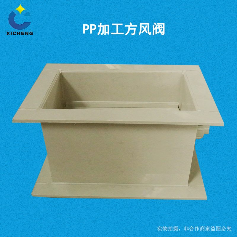
PP Processing Air Valve
| Product Model | PP board welded rectangular multi-leaf control valve |
|---|---|
| Category | PP Machined Products |
| Reference Price | Price on request |
Product Overview
The PP processed square damper is a plate-welded air volume regulating valve installed in rectangular anti-corrosion air ducts. The valve body is formed by folding and welding PP plates into a square frame, with one or multiple vanes inside. The external handle drives the vanes to rotate synchronously through a link mechanism, changing the cross-sectional ventilation area of the rectangle to achieve air volume regulation and actuation. The square damper matches the cross-section of the rectangular duct and connects via square flanges, making it the primary regulating component for laboratory and workshop rectangular exhaust systems.
For larger rectangular cross-sectional dimensions, a single vane spans a wide area with poor rigidity. Therefore, square dampers typically adopt a multi-vane structure, where multiple narrow vanes are arranged vertically. Each vane is fixed to a small vane shaft, with linkage cranks installed at the end of each shaft. A single link connects all Crank, ensuring that when the handle is turned, all vanes open or close synchronously and at the same angle, providing uniform opening and effortless operation. When the multi-vane damper is closed, the vane edges overlap, offering superior air tightness compared to single large-area dampers.
Xicheng Environmental can plate-weld PP square dampers according to the rectangular duct cross-sectional dimensions. The number of vanes is determined by the valve height, with square flanges matching the square tubes. Sealing strips can be added to the vane edges, and the handle includes an opening scale and lock. The product is widely used for laboratory fume hood exhaust, rectangular ducts in electroplating workshops, and square exhaust pipes in suspended ceilings for air volume balancing.
Working Principle
The multi-vane square damper changes the rectangular flow area by Interconnection vanes. When the external handle is rotated, the active vane shaft rotates, and the Crank at the shaft end transmits the motion synchronously to the remaining vane shafts through a link, causing all vanes to rotate at the same angle. When the vanes are closed, the edges of the blades overlap to seal the cross-section. When open, the blades align parallel to the airflow, forming multiple parallel airflow gaps at intermediate angles. Air flows uniformly through these gaps, with resistance varying continuously with the opening degree.
Compared to single large-area dampers, the multi-vane structure divides the large vane area into multiple narrow blades. Each vane has a small span and strong rigidity, resulting in low aerodynamic torque and minimal vibration. The synchronization of all blades is ensured by the mechanism. The PP material and vanes are acid and alkali resistant. The square valve body is welded or flanged to the rectangular duct using the same material, ensuring continuous corrosion resistance for the system. The Interlocking Pivot and shaft sleeves are made of corrosion-resistant materials to guarantee smooth rotation in corrosive gas environments.
Structural Components
The square damper consists of a rectangular valve body, vanes, vane shafts,Linkage Rod,Crank, handle, and flanges. The valve body is formed by folding and welding four PP plates into a square frame, with square flanges welded at both ends. The vanes are narrow, long PP plate segments arranged parallel along the valve height. Each vane is mounted on a vane shaft, with both ends supported by the valve body side wall shaft holes.
The Crank is installed at the end of the vane shaft on the same side, with all Crank connected by a single vertical link, forming a parallel four-bar Interconnection mechanism. One vane shaft is connected to the external handle and an opening scale. Turning the handle drives all vanes. Sealing strips can be added to the vane edges and ends for sealing when closed. For larger cross-sectional areas,Reinforcement rib are added to the valve body exterior, and the vanes can be designed with Edge folding or arched cross-sections to enhance rigidity.
Specification Model Table
The following table provides the vane configuration and connection details for the square damper, matching the cross-sectional dimensions of the rectangular ducts.
| Section Size | Vane Type | Features |
|---|---|---|
| Small Section | Single Vane | Simple Structure |
| Medium-Large Section | Multi-Vane Linkage | Effortless, Uniform Opening |
| Sealing Type | Multi-Vane with Sealing Strips | More Sealed Closure |
Product Features
The PP processed square damper features multi-vane linkage and uniform opening, making it a specialized regulating valve for rectangular anti-corrosion ducts and fume hood exhaust. Key features include:
- PP plate-welded rectangular valve body, acid and alkali resistant
- Multi-vane linkage ensures consistent actuation and uniform opening
- Narrow vanes with small span and strong rigidity, stable under high pressure
- Blade overlap for sealed closure, superior to single square dampers
- Square flanges for easy installation with rectangular ducts
- Customizable section size and vane count to match non-standard ducts
- Handle with opening lock, also available with electric actuators
| Body Material | PP Sheet |
|---|---|
| Processing Technology | Panel welding assembly |
| Section Shape | Rectangle |
| Valve Leaf Form | Single-piece / Multi-leaf linkage |
| Drive Type | Hand-operated handle link |
| Connection Method | Square Flange |
| Corrosion resistance performance | Acid and Alkali Salt Resistant |
| Sealing Options | Leaflet edge soft seal |
| Specifications and Features | Non-standard custom section size |
| Sheet Thickness | Select according to section size |
| Electric Options | Support electric actuator retrofitting |
Application Industries
- Rectangular duct regulating valves for laboratory fume hood exhaust
- End damper for laboratory variable air volume exhaust systems
- Multi-leaf regulating valves for rectangular exhaust main ducts in electroplating workshops
- Square duct air volume balancing dampers for suspended ceilings and interlayers
- Rectangular partition dampers for stratified connections in ventilation shafts
- Regulating air dampers for large rectangular exhaust equipment inlet and outlet
- Non-standard corrosion-resistant duct valves for rectangular cross-section dimensions
Typical Process Locations
Processing dampers are installed on branch ducts, terminations, and main ducts of rectangular ducts. In laboratory fume hood exhaust systems, one square damper is set at the outlet or branch/main duct of each fume hood to adjust the exhaust volume and face velocity of each cabinet. Large-section multi-leaf valves are installed on rectangular main ducts to regulate regional air volume. Valves are connected to square pipes via square flanges, with the operating handle oriented toward maintenance channels. The valve shaft should be installed horizontally to ensure even weight distribution of the valve leaf.
During commissioning, adjust the valve leaf opening and lock the handle in coordination with face velocity or air volume measurements to achieve the designed air volume at each exhaust point. The linkage mechanism of multi-leaf valves is located outside the valve body; sufficient maintenance space must be left to avoid wall-mounted installations that prevent linkage adjustment. For automated control applications, electric actuators can replace handles on the active valve shaft to form electric multi-leaf regulating valves. Before installation, verify the rectangular interface dimensions and flange hole positions. Ensure the valve leaf rotates freely without sticking, and align the valve body with the square pipe before fixing the bracket. During electric retrofitting, match actuator torque with the number of valve leaves, and debug wiring and limit switches in a shutdown state. Regularly inspect linkage pins and seals during operation, and promptly adjust or replace them if Loosen or air leakage is detected.
Related Products
View More Hot
Hot
PP Fire-Resistant Analog Air Valve
 Hot
Hot
PP Fire-Resistant Closed-Check Valve
 Hot
Hot
PP Flame Retardant Additive Drum
 Hot
Hot
PP Flame Retardant Processed T-Connector
Get Quote
PP Flame Retardant Processed T-Connector / PP board welded rectangular multi-leaf control valve