
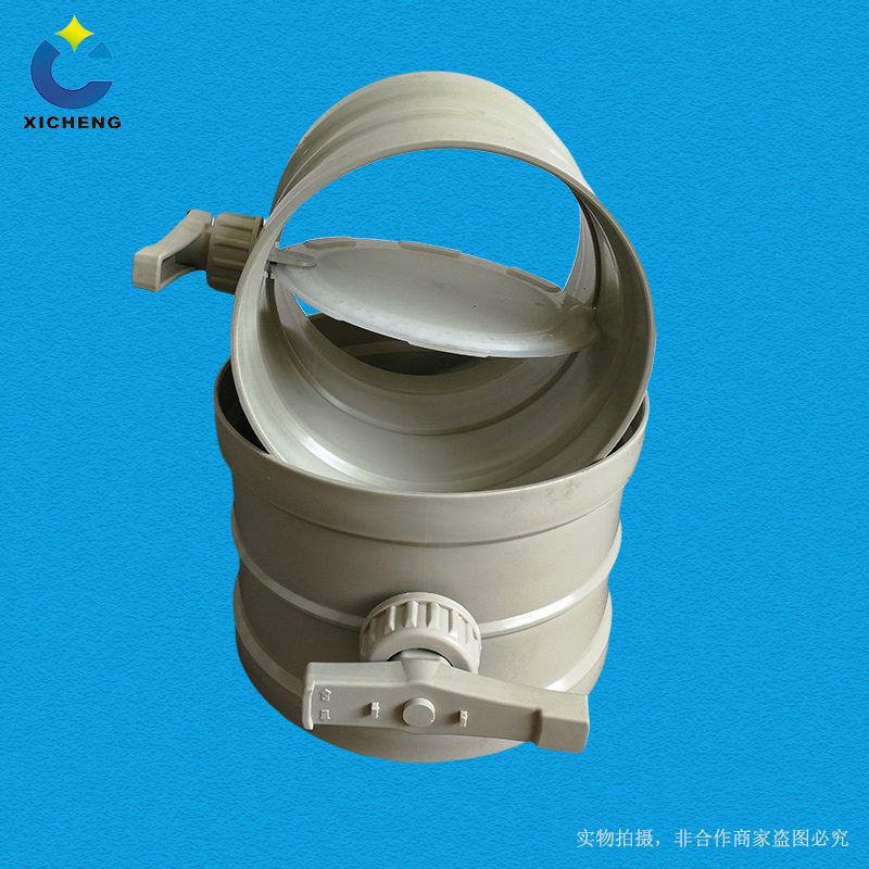
PP Closed Damper
| Product Model | PP Manual Soft Seal Closed Valve |
|---|---|
| Category | PP Machined Products |
| Reference Price | Price on request |
Product Overview
The PP hermetic damper is a manually operated corrosion-resistant damper with soft sealing for high air-tight closure. It is used in ductwork locations that need to remain open under normal conditions but require manual closure for maintenance or shutdown. Unlike conventional manual regulating dampers, the hermetic damper features a soft seal ring on the vane, which is pressed against the seat by a handle locking mechanism when closing, resulting in minimal air leakage and reliable isolation of the pipe section. In contrast, conventional regulating dampers still have a noticeable gap even when fully closed.
In corrosion-resistant exhaust systems, not all isolation points require power supply and automatic control. For example, isolation valves near equipment inspection ports, cut-off valves for long-term standby branches of parallel equipment, and isolation valves for seasonally inactive pipe sections. These valves have low actuation frequency and manual operation conditions, making manual hermetic dampers more cost-effective than electric hermetic dampers, with simpler structures and no reliance on power sources. The soft sealing closure remains equally reliable.
The PP hermetic dampers supplied by Xichen Environmental are available in formed or plate-welded bodies, with corrosion-resistant soft seal rings embedded at the vane edges. They are equipped with a manual handle featuring locking and pressing mechanisms. Available in circular, square, and various sizes, they can be made of PPs material for flame-retardant requirements. The handle can be locked after full closure to prevent accidental opening, making them suitable as maintenance isolation dampers for corrosion-resistant exhaust systems.
Working Principle
Manual hermetic dampers achieve air-tightness through soft sealing and mechanical pressing. When closure is required, the operator turns the handle to move the vane to the closed position. Continuing to operate the handle engages an eccentric, four-bar, or screw-type pressing mechanism to uniformly press the vane seal against the body seat, causing the elastic seal to deform and fill the gap. The handle is then locked to maintain the pressing state, reliably cutting off airflow. For opening, the lock is released, the pressing is loosened, and the vane is rotated to the fully open position.
Different from conventional manual valves, hermetic dampers require distinct pressing and locking actions to ensure low leakage. The PP vane and body are acid and alkali-resistant, with sealed shaft seats to prevent external leakage. The seal ring is selected for compatibility with exhaust gases and corrosion-resistant elasticity, maintaining long-term elasticity. When fully open, the vane aligns parallel to the airflow, and the seal ring detaches from the seat, avoiding continuous airflow erosion, which helps extend the seal life.
Structural Components
The manual hermetic damper consists of a body, a sealed vane, a shaft, a seat, a pressing and locking handle, and end connections. The body is a PP-formed cylinder or plate-welded cylindrical shell with a flat seat at the full-closure position. The vane is a rigid plate with corrosion-resistant soft seal rings embedded at the edges and fixed to the shaft. The shaft is supported by a sealed shaft seat, with one end extending from the body to connect to the operating mechanism.
The operating mechanism is not a conventional straight-through handle but a handle or handwheel with eccentric pressing or four-bar locking. At the closing end, it presses the vane against the seat and locks it. Some large-diameter valves use a screw pressing mechanism for forceful and reliable operation. Square hermetic dampers feature multi-leaf vanes with circumferential sealing and leaf overlap sealing, synchronized by linkages and pressed by the handle. The body connections are socket or flange, with optional locking holes to prevent accidental operation.
Specification Model Table
The following table compares manual hermetic dampers with manual regulating dampers for selection based on isolation requirements.
| Item | Manual Hermetic Damper | Manual Regulating Damper |
|---|---|---|
| Sealing | Soft ring pressed and locked | Hard contact with gap |
| Operation | Rotation plus pressing | Rotation to position |
| Purpose | Maintenance isolation | Airflow balancing adjustment |
| Actuation Frequency | Infrequent operation | Adjustment during commissioning |
Product Features
The PP hermetic damper features soft sealing with locking, reliable isolation, and no reliance on power, making it an economical choice for maintenance isolation in corrosion-resistant ductwork. Key features include:
- Soft seal ring pressed against the seat, minimizing air leakage at full closure
- Handle locks the pressing mechanism to prevent accidental contact and self-loosening
- Manual operation without power or compressed air, simple and reliable structure
- PP or PPs material, acid and alkali-resistant with flame-retardant options
- Suitable for infrequently actuated maintenance isolation and standby branches
- Lower cost than electric hermetic dampers, minimal maintenance requirements
- Available in circular, square, and various sizes; custom non-standard options
| Body Material | PP / PPs |
|---|---|
| Sealing Form | Soft Seal Ring Compression |
| Drive Type | Manual handle clamping and locking |
| Fully Automatic Performance | Low-leakage air-tight partition |
| Corrosion resistance performance | Acid and Alkali Salt Resistant |
| Sealing Selection | By Media Compatibility |
| Locking function | Handle can be locked |
| Connection Method | `Spigot / Flange` |
| Applicable Frequency | Infrequent operation |
| Flame Retardant Options | PPs self-extinguishing |
| Electric Options | Electric Actuator |
Application Industries
- Manual isolation valves for import/export maintenance of flue gas treatment equipment
- Branch isolation valves for parallel standby fans and standby stacks
- Manual airtight valves for seasonal shutdown production line exhaust branches
- Manual isolation valves for duct maintenance in fan rooms
- Manual airtight isolation for zoned laboratory exhaust systems
- Locations requiring prevention of cross-flow in shutdown pipelines
- Corrosion-resistant ducts requiring airtight closure without power supply
Typical Process Locations
Manual airtight dampers are installed at positions that are normally open, requiring manual closure during maintenance or shutdown. They are typically placed close to the equipment's import/export points, leaving sufficient space for maintenance operations. The handle position should allow easy access and forceful locking by personnel. During equipment maintenance, the airtight dampers are closed before and after to isolate harmful gases. When necessary, venting or inspection ports are installed between the valve and equipment to confirm effective isolation before proceeding. Long-unused branches should have their airtight valves closed to prevent air short-circuiting and cross-flavoring.
During installation, the valve body's airflow direction indicator determines the orientation to ensure air pressure assists the seal. The valve shaft should be installed horizontally, and pipe supports must bear the weight to prevent deformation of the valve body. Operation training should emphasize that the airtight damper must be tightened after closing, not just rotated to the fully closed position and stopped. During regular inspections, check the handle locking status and the aging condition of the sealing ring. After maintenance isolation use, record the valve's open/close status to prevent accidental operation.
Related Products
View More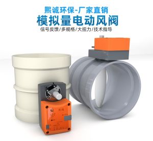 Hot
Hot
PP Fire-Resistant Analog Air Valve
 Hot
Hot
PP Fire-Resistant Closed-Check Valve
 Hot
Hot
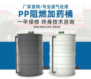
PP Flame Retardant Additive Drum
 Hot
Hot
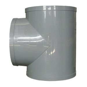
PP Flame Retardant Processed T-Connector
Get Quote
PP Flame Retardant Processed T-Connector / PP Manual Soft Seal Closed Valve