
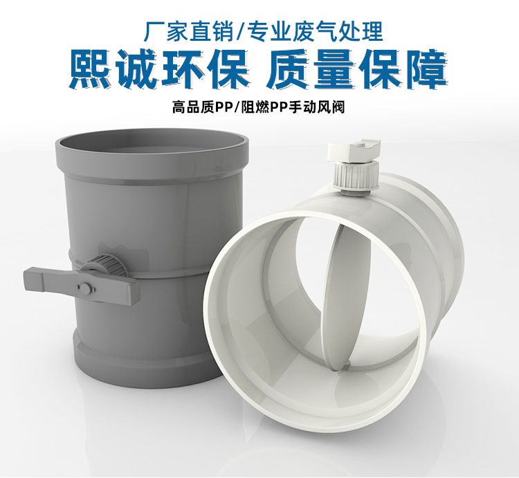
PP Manual Damper
| Product Model | Forming Manual Adjustment Damper |
|---|---|
| Category | PP Molded Products |
| Reference Price | Price on request |
Product Overview
The PP manual damper is a plastic valve installed in corrosion-resistant ventilation pipelines, used for manual adjustment of airflow and opening/closing air channels. The valve body and vane are molded from PP or PPs, offering acid and alkali resistance. The external handle drives the valve shaft to rotate, changing the vane angle within the pipeline cross-section, thereby adjusting the flow area and airflow volume. It serves as a fundamental component for airflow balancing and branch regulation in exhaust systems.
In multi-branch exhaust systems, the distances from each collection point to the fan vary, resulting in significant resistance differences. Manual dampers must be installed on each branch for initial airflow balancing, ensuring that each extraction point receives the designed airflow. With a simple structure, low cost, and intuitive adjustment, technicians can turn the handle to adjust the opening and lock the position, making it suitable for infrequent adjustments and primarily for balancing purposes in ventilation pipelines.
The PP manual dampers supplied by Xichen Environmental are molded valve bodies, compatible with molded pipeline diameters. They are available in standard PP and flame-retardant PPs materials, with options for circular or square shapes and spigot or flange connections. The vane rotates smoothly and closes tightly, with a sealing structure at the valve shaft to reduce air leakage. The handle features an opening indicator and locking mechanism, facilitating the recording of adjustment angles.
Working Principle
The manual damper adjusts airflow by changing the vane angle. The vane is either circular or square and rotates around the valve shaft within the valve body. When perpendicular to the pipeline axis, the valve is fully closed with the minimum flow area, and when parallel, the valve is fully open with the maximum flow area. Intermediate angles correspond to different openings. Turning the handle drives the valve shaft to rotate the vane, continuously adjusting the flow area and achieving airflow regulation from fully closed to fully open.
The fundamental principle of damper airflow adjustment is to change the local resistance in the pipeline. Reducing the vane opening increases the local resistance coefficient. Under the fan's characteristic curve, this reduces airflow in the branch, while excess airflow is distributed to other branches, achieving airflow balance. The PP valve body and vane are resistant to acid and alkali exhaust corrosion. Even in corrosive environments, the vane maintains its shape and gap, with rust-free sealing edges, ensuring stable adjustment and closing performance.
Structural Components
The manual damper consists of a valve body, vane, valve shaft, shaft seat seal, handle, and opening locking mechanism. The valve body is a molded cylinder or square frame, connected to pipelines via spigot or flange joints at both ends. The vane is located in the middle of the valve body and is fixed to the shaft for rotation. The shaft is supported by external shaft seats with seals to prevent air leakage through the shaft holes. The valve body exterior is equipped with a handle and scale.
The handle is the operating component of the manual damper, commonly driving a four-bar linkage or directly rotating the valve shaft. After reaching the desired angle, it is locked in place by a set screw or positioning teeth. The vane edges can be fitted with a soft sealing gasket, which seals against the inner wall of the valve body when fully closed to improve air tightness. Square dampers have a similar structure, with vane blades in rectangular shapes. Large-diameter dampers may include a bearing seat to reduce rotation torque.
Specification Model Table
The following table describes the forms and connections of manual dampers, with diameters matching pipeline series.
| Form | Connection | Applicable Case |
|---|---|---|
| Circular Manual Damper | Spigot / Flange | Circular Pipeline Branch |
| Square Manual Damper | Flange | Square Pipeline Branch |
| Flame-Retardant Manual Damper | Spigot / Flange | Fire-Resistant Indoor Pipeline |
Product Features
The PP manual damper features a simple structure and intuitive adjustment, serving as a fundamental component for corrosion-resistant exhaust system airflow balancing. Key features include:
- PP or PPs molded, resistant to acid and alkali exhaust corrosion
- Handle directly adjusts opening, intuitive operation without power supply
- Smoothly rotating vane with locked opening position
- Opening indicator for easy debugging and airflow balance recording
- Shaft seal reduces air leakage, soft seal ensures tight closure
- Compatible with molded pipelines, convenient spigot or flange connections
- Simple structure, low cost, minimal maintenance, long service life
| Body Material | PP / PPs Polypropylene |
|---|---|
| Molding Process | Injection Molding |
| Drive Type | Manual Handle |
| Adjustment Parts | Rotating Valve Disc |
| Function | Flow Rate Adjustment / On/Off Control |
| Connection Method | `Spigot / Flange` |
| Corrosion resistance performance | Acid and Alkali Exhaust Gas |
| Lock Open Degree | With locking mechanism |
| Flame Retardant Options | PPs self-extinguishing |
| Sealing Options | Valve Disc Edge Sealing |
| Specifications Range | Stock available for common sizes |
Application Industries
- Flow balance regulation for exhaust branch pipes in electroplating workshops
- Branch air dampers for chemical acid/alkali exhaust gas collection systems
- Branch Adjustment valves for fume hoods and exhaust hoods in laboratories
- Flow distribution for acid/alkali exhaust systems in semiconductor factories
- Branch Adjustment air dampers for gas collection hoods in metallurgical pickling lines
- Inspection isolation dampers for inlet and outlet air ducts of spray towers
- Branch Adjustment valves for odor collection branches in wastewater treatment plants
Typical Process Locations
Manual air dampers are primarily installed near branch pipes and gas collection points in exhaust systems. One damper is set downstream of each gas hood, ventilation cabinet, or equipment exhaust connection for adjusting flow rates at various points during system commissioning. Manual dampers can also be installed on main pipelines and equipment inlet/outlet connections as maintenance isolation valves. The damper position should be selected at a height suitable for operation, easily accessible, and with space for handle rotation. Operation space must be reserved.
During system commissioning, after the fan starts, an anemometer measures flow rates at each exhaust point. Starting from the most disadvantageous point, the manual branch damper openings are adjusted individually until the design flow rates are achieved, then the handles are locked and the openings are recorded. During operation, manual dampers generally remain in the commissioned position. When localized shutdown maintenance is required, the corresponding branch valve is closed. Manual dampers are not suitable for applications requiring automatic control or frequent operation; electric dampers should be selected for such needs. Before installation, verify the size and connection method, rotate the handle to confirm full-range smooth valve vane rotation and accurate opening indication, then align and secure with the pipeline. After commissioning, mark the normal open or closed position on the valve body or handle. During operation, the valve generally remains at the commissioned opening. When isolation is needed, close fully and lock. Regularly inspect valve vane sealing and handle locking mechanisms. Clean the shaft sleeve and edges if dust or jamming occurs.
Related Products
View More Hot
Hot
PVC Flexible Duct Connector
 Hot
Hot
PVC Plastic Damper
 Hot
Hot
PP plastic ring
 Hot
Hot
PP Equipment Window
Get Quote
PP Equipment Window / Forming Manual Adjustment Damper