
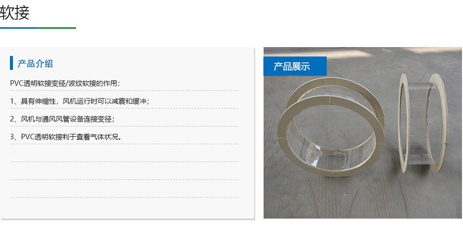
PVC Flexible Duct Connector
| Product Model | Transparent corrugated soft connector series |
|---|---|
| Category | PP Molded Products |
| Reference Price | Price on request |
Product Overview
PVC soft joint is a corrugated flexible pipe connector made of transparent or semi-transparent PVC, connecting both ends to air ducts or equipment interfaces. The soft Connector utilizes the Retractable and bending capabilities of its corrugated segments to absorb vibrations generated by fan operation and installation deviations in pipelines, blocking vibration transmission along rigid air ducts. It can also serve as a variable diameter connection for fan inlet and outlet, making it a commonly used flexible connector in ventilation systems.
Transparency is a standout feature of PVC soft joint. Through the soft joint wall, operators can directly observe internal gas flow, water mist carryover, and liquid accumulation, enabling judgment of fan and upstream equipment operating conditions—advantages not possessed by opaque canvas or metal soft joints. The soft Connector also offers certain acid and alkali resistance, suitable for ventilation systems with low corrosivity. It is lightweight, easy to install, and cost-effective.
PVC soft joints supplied by Xicheng Environmental Protection are available in straight-tubular corrugated and variable-diameter corrugated forms, fixed to air ducts via clamps, flanges, or bands. The product is primarily used for vibration reduction at fan inlet and outlet, flexible transition between equipment and pipelines, and pipe sections requiring internal observation. For highly corrosive environments, PP or corrosion-resistant soft joints should be selected, while high-temperature applications require temperature-resistant soft joints.
Working Principle
The vibration isolation principle of the soft Connector is flexible isolation. When a fan operates, its impeller and motor generate vibrations. If the fan is rigidly connected to the air duct, vibrations will transmit along the duct and supports, causing pipeline resonance, noise, and interface loosening. The low stiffness of the corrugated flexible segment of the soft Connector allows deformation in axial extension, radial misalignment, and angular deviation, absorbing vibration displacement and attenuating vibration energy—effectively creating an isolation break between the fan and the air duct.
The variable diameter and compensation principles of the soft Connector stem from the deformability of its corrugated segment. When equipment inlet/outlet diameters differ from air duct sizes, variable-diameter soft joints provide smooth transitions via conical corrugated segments. For minor installation misalignments or thermal expansion/contraction in pipelines, the soft joint compensates for deviations through extension and deflection, reducing installation stress. The transparent PVC wall does not obstruct visibility, allowing light to penetrate the pipe, enabling observation of internal water mist, dust accumulation, and liquid buildup from the exterior.
Structural Composition
PVC soft joints consist of a flexible corrugated segment and two end connection/fixation parts. The corrugated segment has its wall pressed into a circular wave pattern, which grants the component Retractable and bending capabilities while maintaining a circular cross-section to prevent collapse under fan suction. The two ends are either smooth or thickened, designed to fit over air ducts and be secured with clamps or bands, or to be pressed against flanges for fixation.
Variable-diameter soft joints have one end with a larger diameter and the other with a smaller one, transitioning via conical corrugated segments, used for connecting fans to air ducts of different diameters. Straight-tubular soft joints have identical diameters at both ends and primarily serve vibration isolation and compensation functions. The length of the soft joint is selected based on required compensation and vibration reduction needs. The end clamps are typically metal components, and in highly corrosive environments, they can be treated for corrosion resistance or replaced with plastic clamps.
Specification Model Table
The table below lists soft joint forms and their primary functions, with pipe diameters matching fan and air duct interfaces.
| Form | Primary Function | Typical Location |
|---|---|---|
| Straight-tubular soft joint | Vibration isolation and compensation | Fan inlet/outlet with same diameter |
| Variable-diameter soft joint | Vibration isolation with variable diameter | Fan inlet/outlet with different diameters |
| Transparent soft joint | Vibration isolation with observation | Pipe sections requiring internal observation |
Product Features
PVC soft joints integrate vibration isolation, variable diameter, compensation, and observation functions, making them a common accessory for fan connections. Key features include:
- Corrugated flexible segment extends and deflects to effectively isolate fan vibrations
- Blocks vibration transmission, reducing pipeline resonance and noise
- Transparent wall allows observation of internal gas flow, water mist, and liquid accumulation
- Variable-diameter form serves as a transition for fan inlet/outlet with different diameters
- Compensates for installation deviations and thermal expansion/contraction, reducing stress
- Lightweight, with quick and easy installation via clamps or bands for replacement
- Offers certain acid and alkali resistance, with cost-effective pricing
| Material | PVC 聚氯乙烯 |
|---|---|
| Tube wall features | Transparent corrugated flexible section |
| Form | Straight tube / Tapered tube |
| Connection Method | Clamp / Strainer / Flange |
| Function | Shock Absorber Diameter Adjustment Compensation Observation |
| Corrosion resistance performance | Resistance to general acids and alkalis |
| Formability | Axial extension Radial deflection |
| Installation Location | Between the fan and the ductwork |
| Color | Transparent / Off-White |
| Temperature Range | Room Temperature Exhaust |
| Fasteners | Clamp Band |
Application Industries
- Shock absorption soft joints between corrosion-resistant fan inlets and ducts
- Conical joints for connecting fan outlets to main ducts with different diameters
- Flexible vibration isolation for fan sections in spray towers and washing towers
- Soft joints between laboratory exhaust fans and plastic ducts
- Exhaust stacks requiring observation of internal water mist accumulation
- Vibration isolation joints between equipment and pipelines with significant vibration
- Flexible compensation segments for pipeline installation with misalignment deviations
Typical Installation Locations
The most typical locations for soft joints are the inlets and outlets of fans. Fan inlet soft joints connect intake ducts or equipment outlets, while fan outlet soft joints connect exhaust main ducts. These two soft joints isolate the fan body from rigid ducts to prevent vibration transmission to the pipeline network. Soft joints should be installed near the fan body, securely fastened with clamps at both ends, and maintained in a natural state without being stretched to the limit or compressed into deformation.
In sections requiring observation, transparent soft joints are installed at spray tower outlets, after demisters, or at fan inlets. Operators can inspect the water and dust accumulation through the pipe wall to assess demisting effectiveness. Soft joints cannot replace fixed pipeline load-bearing capacity; independent support brackets should be installed on both ends of the pipelines and equipment. Soft joints remain in a free Retractable state. During maintenance, clamps can be loosened to replace the soft joint. Before installation, verify the fan and duct diameters, straight or conical forms, ensure alignment of both ends of the pipelines with misalignment deviations within the soft joint compensation range, evenly tighten clamps or flanges, and retain the natural relaxed arc of the soft joint segment without forced stretching or twisting. Soft joints do not bear pipeline and equipment weight; independent support brackets should be installed on both ends of the pipelines. During operation, inspect the corrugated sections for collapse, bulging, and aging cracking. Replace immediately if hardening or tearing is detected.
Related Products
View More Hot
Hot
PVC Plastic Damper
 Hot
Hot
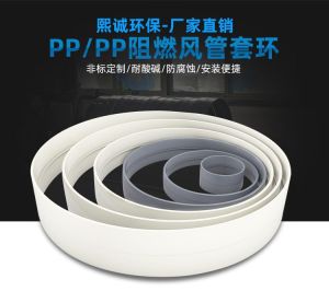
PP plastic ring
 Hot
Hot
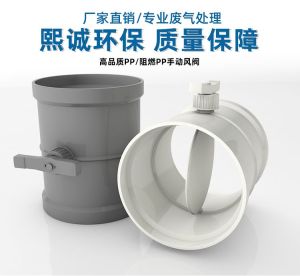
PP Manual Damper
 Hot
Hot
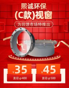
PP Equipment Window
Get Quote
PP Equipment Window / Transparent corrugated soft connector series