
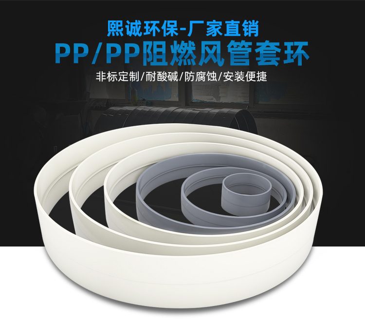
PP plastic ring
| Product Model | Injection Molded Spigot Ring Series |
|---|---|
| Category | PP Molded Products |
| Reference Price | Price on request |
Product Overview
PP sleeve rings, also known as direct or sleeve joints, are tubular connecting components with承口 at both ends, specifically designed for axial splicing of two sections of PP air ducts with the same diameter. During installation, each section of the air duct is inserted into one end of the sleeve ring, aligned, and then sealed with PP welding rods at the承口. This achieves pipe extension. The sleeve ring features a simple structure and low cost, making it a widely used standard component in straight splicing of corrosion-resistant ventilation pipes.
The sleeve ring is molded in one piece using injection molding technology, resulting in a seamless, uniformly thick wall. The inner surface aligns smoothly with the inner wall of the air duct, eliminating pronounced steps or ledges at the connection point, thereby minimizing airflow resistance and reducing dust accumulation. Compared to flange connections, sleeve ring connections offer a cleaner appearance and lower cost, making them suitable for fixed pipe sections that do not require disassembly. Compared to direct welding, sleeve ring承插定位 is easier and provides more stable alignment quality.
The PP sleeve rings supplied by Xicheng Environmental Protection are matched with the diameter series of formed air ducts and are available in both standard PP and flame-retardant PP materials. Flame-retardant sleeve rings, when used with PP air ducts, also exhibit self-extinguishing properties at the joint, ensuring fire consistency throughout the entire pipeline. Sleeve rings can also be used to connect air ducts to equipment interfaces with 承口.
Working Principle
Sleeve ring connections achieve sealing and fixation through 承插 plus welding. The inner diameter of the sleeve ring is slightly larger than the outer diameter of the air duct, forming a 承插配合. After insertion, the ends of the two air duct sections align at the center of the sleeve ring. The 承口 restricts radial misalignment of the air ducts, keeping the pipeline straight. The gap at the 承口 is sealed using a hot air welding gun and PP welding rods. The weld closes along the circular periphery of the sleeve ring's end, melting three plastic sections into one, preventing gas from escaping at the joint.
The 承插 structure enhances the load-bearing capacity of the joint. When the air ducts are subjected to wind pressure or slight vibration, the sleeve ring encases the pipe ends, with the weld primarily responsible for sealing, while axial and radial loads are distributed by the 承插配合 surface. This provides stronger anti-deformation capabilities compared to simple direct welding. The thermal expansion coefficients of PP sleeve rings and air ducts are identical, allowing them to expand and contract synchronously with temperature changes, preventing cracks at the joint due to uneven expansion or contraction.
Structural Composition
The PP sleeve ring consists of a short tube with a thickened 承口 at both ends. The inner diameter of the 承口 matches the outer diameter of the air duct, and a positioning step or equal-diameter straight cavity is provided at the center. The outer wall of the 承口 may feature a circumferential reinforcement ring to enhance rigidity, and the ends are chamfered for easier air duct insertion. The sleeve ring is molded in one piece, resulting in smooth inner and outer walls. Its length increases with the diameter to ensure sufficient 承插 depth and weld positioning.
Flame-retardant sleeve rings incorporate flame-retardant additives into the raw material, resembling standard sleeve rings in appearance but with self-extinguishing properties. The sleeve ring itself does not include components such as bolts or gaskets; only PP welding rods and a hot air welding gun are required for connection. For sections requiring inspection or disassembly, sleeve rings are not suitable, and flange connections should be used instead.
Specification Model Table
The table below shows the connection type and applicable locations of the sleeve rings, with diameters corresponding to formed air duct series.
| Type | Connection Method | Applicable Location |
|---|---|---|
| Standard PP Sleeve Ring | 承插 Welding | General Acid-Alkali Exhaust |
| Flame-Retardant PP Sleeve Ring | 承插 Welding | Indoor Fire-Resistant Air Ducts |
| Thickened Sleeve Ring | 承插 Welding | Large-Diameter Main Pipes |
Product Features
PP sleeve ring connections are straight and fast to install, making them an economical solution for fixed straight sections of air ducts. Key features include:
- Injection-molded in one piece, seamless, and fully corrosion-resistant
- Two-end 承插 positioning ensures straight pipe alignment and quick installation
- Smooth inner surface reduces airflow resistance and prevents dust accumulation or contamination
- Combination of 承插 and welding provides dual protection for excellent sealing and crack resistance
- Simple structure, lightweight, and lower cost than flange connections
- Specifications match formed air ducts, with flame-retardant material options available
- Expands and contracts synchronously with air ducts, excellent temperature adaptability
| Material | PP / PPs Polypropylene |
|---|---|
| Molding Process | Integral injection molding |
| Connection Method | Two-end socket welding |
| Applicable Pipes | PP Duct with Same Flange |
| Corrosion resistance performance | Acid-alkali-resistant salt |
| Flame Retardant Options | PPs self-extinguishing |
| Inner wall features | Seamless connection with ductwork |
| Removability | Fixed connection, non-detachable |
| Function | Tube splicing reinforcement |
| Matching Port | Multiple size options available |
| Sealing Features | Welded Seam Connection Sealing |
Application Industries
- Linear extension and splicing of straight ducts in acid-alkali exhaust systems of electroplating workshops
- Fixed pipe section connections of exhaust air ducts in chemical enterprises
- Direct pipe connections in acid-alkali exhaust systems of semiconductor factories
- Segment connections between laboratory exhaust shafts and horizontal main ducts
- On-site splicing of corrosion-resistant exhaust ducts in metallurgical pickling lines
- Extended connections of odor collection pipelines in wastewater treatment plants
- Fixed section connections of tail gas emission ducts in pharmaceutical factories
Typical Process Locations
Collars are used for straight duct sections in ventilation systems that do not require disassembly, commonly found in horizontal main ducts along supports and vertical shafts. Due to the limited single length of standard formed ducts, collars are used for point-to-point connections over long distances. The collar is positioned between two hangers or near the support, forming a continuous and integrated pipeline after connection. Collars are not used for equipment inlets/outlets or areas requiring frequent maintenance.
In exhaust collection systems, the collared pipe sections are located in the transport paths between hood branch ducts and main ducts, as well as between main ducts and purification equipment. During installation, one end of the duct is fixed, the collar is inserted, and the other end is connected after alignment and leveling, followed by sealing along the flange circumference. Removable sections near fans and equipment are connected with flanges, while fixed transport sections primarily use collars to balance sealing performance and cost-effectiveness. Before collaring, verify that the outer diameters of both duct ends match the collar inner diameter, ensure uniform insertion depth and consistent annular gaps, and clean/dry the flanges before symmetrical welding around the circumference to avoid offset caused by unilateral buildup. Collared sections are positioned between two hangers and temporarily fixed, with sealing integrity checked after welding. Areas near fan vibration zones and those requiring disassembly are not connected with collars but instead use flanges or flexible connections.
Related Products
View More Hot
Hot
PVC Flexible Duct Connector
 Hot
Hot
PVC Plastic Damper
 Hot
Hot
PP Manual Damper
 Hot
Hot
PP Equipment Window
Get Quote
PP Equipment Window / Injection Molded Spigot Ring Series