
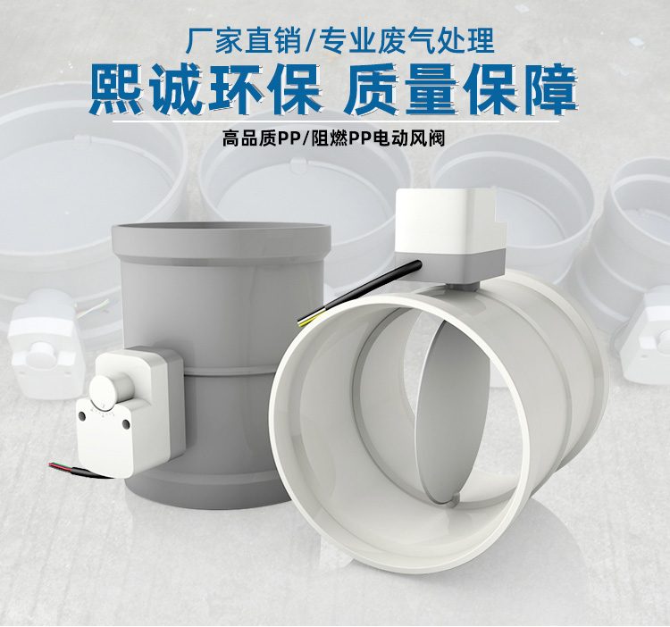
PP Fire-Resistant Electric Damper
| Product Model | PPs Formed Electric Air Valve |
|---|---|
| Category | PP Machined Products |
| Reference Price | Price on request |
Product Overview
The PP Flame-Retardant Electric Damper is a standard-sized automatic air damper equipped with an electric actuator, assembled onto a flame-retardant PP injection-molded valve body. Compared to plate-welded electric dampers, the molded valve body features standardized dimensions, uniform wall thickness, fast delivery, and cost-effectiveness, making it suitable for indoor corrosion-resistant exhaust duct sections within standard series sizes. Upon receiving an on/off electrical signal, the actuator drives the vane to rotate approximately 90 degrees, enabling remote automatic opening/closing of the air duct and interlocking control with fans and equipment.
The flame-retardant PPs valve body is resistant to acid and alkali gas corrosion and exhibits self-extinguishing properties, making it ideal for corrosion-resistant exhaust systems installed indoors, suspended ceilings, and pipe shafts. Electric dampers are commonly used in exhaust branch pipes requiring automatic on/off operation with production equipment, interlocking dampers at fan inlets/outlets, and remote isolation dampers in unattended areas, eliminating the need for operators to manually switch valves on-site, thereby enhancing the automation level of exhaust systems and preventing gas backflow during shutdown.
The PP flame-retardant electric dampers supplied by Xicheng Environmental Protection are standard round-shaped openings, compatible with PPs molded ducts, and connected via slip-fit or flange joints. They are equipped with on/off electric actuators featuring full-open/full-close position feedback, and the actuators can include a manual operation knob. For applications requiring continuous airflow regulation, analog modulating dampers should be selected. For large diameters or non-standard sizes, plate-welded electric dampers are recommended.
Working Principle
In an on/off electric damper, the motor inside the actuator drives the output shaft to rotate between 0 and 90 degrees via a reduction gear. The output shaft, connected via a coupling, synchronizes the rotation of the vane shaft. When the control system issues an open valve signal, the motor drives the vane to the fully open position, at which point an internal limit switch disconnects power and sends an open On-site signal. Conversely, a close valve signal reverses the rotation to the fully closed position. When fully open, the vane aligns parallel to the airflow, minimizing resistance, and when fully closed, it aligns perpendicular to the airflow, sealing the duct.
The corrosion-resistant and flame-retardant performance of the molded PPs valve body and vane is inherent to the material. The vane rotates without rusting or seizing in acid and alkali gases, and the material self-extinguishes without spreading along the pipeline upon ignition. The actuator is installed on the outside of the valve body, isolated from the internal gas stream via a valve shaft seal. A seal ring and wear-resistant bushing are provided between the valve shaft and the valve body's shaft seat, reducing air leakage through the shaft hole while ensuring smooth vane rotation. Actuator torque is selected based on the vane's operating torque under maximum air pressure, with a safety margin added.
Structural Components
The flame-retardant electric damper consists of a PPs molded valve body, vane, shaft, shaft seat seal, electric actuator, mounting bracket, and end connections. The valve body is an injection-molded cylindrical structure with slip-fit or flange ends for compatibility with molded ducts. The vane is a molded circular plate fixed to the shaft, which passes through the valve body and is supported by shaft seats on both sides. The shaft seats are equipped with seal rings and bushings.
The actuator is mounted on the extending end of the shaft via a bracket, which is fixed to the outside of the valve body. The actuator's output shaft is coaxially connected to the valve shaft. The actuator integrates a motor, reduction mechanism, limit switch, feedback contacts, and manual operation mechanism. The junction box has a protection rating suitable for indoor environments. A soft seal strip can be added to the vane edge to improve full-closure air tightness. Standard dampers feature a single vane structure, covering common molded duct series sizes.
Specification Model Table
The following table provides a comparison for selecting molded and plate-welded electric dampers, with diameters matched to duct series.
| Item | Molded Electric Damper | Plate-Welded Electric Damper |
|---|---|---|
| Diameter | Standard series | Large non-standard |
| Delivery | Fast, cost-effective | Drawn to print |
| Application | Indoor standard branch pipes | Main pipes, non-standard sections |
| Material | PPs Flame-Retardant | PP / PPs optional |
Product Features
The PP Flame-Retardant Electric Damper is a standard molded, corrosion-resistant, and flame-retardant automatic valve, commonly used for indoor standard corrosion-resistant exhaust branch pipes. Key features include:
- PPs flame-retardant molded valve body, self-extinguishing, acid/alkali resistant
- Standard diameters with uniform wall thickness, fast delivery, cost-effective
- Remote on/off operation via electric actuator, supports equipment interlocking
- Full-open/full-close position feedback, status monitorable
- Valve shaft seal reduces air leakage, vane rotates smoothly
- Slip-fit or flange connections with molded ducts, quick installation
- Actuator includes manual operation knob, allows adjustment and emergency use
| Body Material | PPs Flame Retardant Polypropylene |
|---|---|
| Molding Process | Injection Molding |
| Section Shape | Round |
| Drive Type | Electric Actuator |
| Control Type | Switching Full On/Full Off |
| Feedback Signal | Fully open and fully close in place |
| Flame Retardancy Performance | Self-extinguishing |
| Corrosion resistance performance | Acid-alkali-resistant salt |
| Connection Method | `Spigot / Flange` |
| Manual operation | Actuator with manual knob |
Application Industries
- Standard branch duct electric switch valves for laboratory exhaust systems
- Standard diameter exhaust synchronous electric valves for electroplating production lines
- Electric valves for indoor PPs forming duct equipment interfaces
- Interlocked standard diameter electric exhaust dampers for fan inlets and outlets
- Remote isolation valves for corrosion-resistant exhaust branch ducts in suspended ceilings
- Standard branch line electric valves for multi-machine shared fans
- Standard corrosion-resistant electric exhaust valves for semiconductor plant facilities
Typical Process Locations
The flame-retardant electric dampers are installed at equipment interfaces, branch ducts, and fan inlets/outlets of indoor standard diameter PPs circular ducts, connected to forming ducts via spigot or flange. The electric valve at the equipment exhaust port operates with the equipment start/stop, while the fan inlets/outlet valves are interlocked with the fan—valves open before startup and close after shutdown. The valve position should ensure the actuator faces the maintenance side, with reserved space for power control wiring and manual operation, avoiding actuator wall contact or placement in water accumulation areas.
During electrical connection, the actuator power is interlocked with the fan or equipment control circuit, and the switch position signal is connected to the control cabinet, with the upper system displaying valve status. The commissioning sequence is: first, operate the valve vane manually without power to confirm full travel flexibility; second, power on and verify the actual vane angle matches the actuator indication at the local switch; finally, perform remote interlock and position feedback joint debugging to ensure the fan does not start when the valve is closed.
For electric valves installed on standard indoor branch pipes and equipment interfaces within the PPs formed duct standard series, choose formed electric valves. They feature standard dimensions, fast delivery, low cost, and good interchangeability. For valves with sizes outside the standard series, used on large-diameter main pipes, or requiring special lengths, special flanges, or non-standard cross-sections, select plate-welded processed electric valves. The vane can be reinforced, the valve shaft thickened, and the actuator torque selection range is wider, allowing them to withstand higher air pressure. Both types operate on the same control principle, where the actuator drives the vane movement. The main differences lie in the size coverage range, structural strength, and delivery cycle. Selection should be based on duct size, air pressure, and installation location, with priority given to processed valves for large sizes, high air pressure, and non-standard applications. It is recommended to standardize connection standards and actuator models within the same system for easier spare parts replacement, wiring, and future maintenance.
Related Products
View More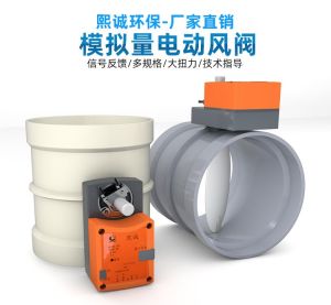 Hot
Hot
PP Fire-Resistant Analog Air Valve
 Hot
Hot
PP Fire-Resistant Closed-Check Valve
 Hot
Hot
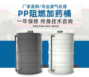
PP Flame Retardant Additive Drum
 Hot
Hot
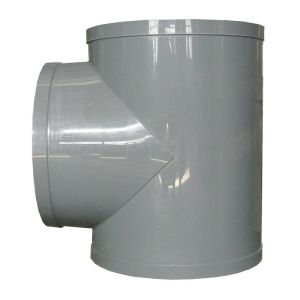
PP Flame Retardant Processed T-Connector
Get Quote
PP Flame Retardant Processed T-Connector / PPs Formed Electric Air Valve