
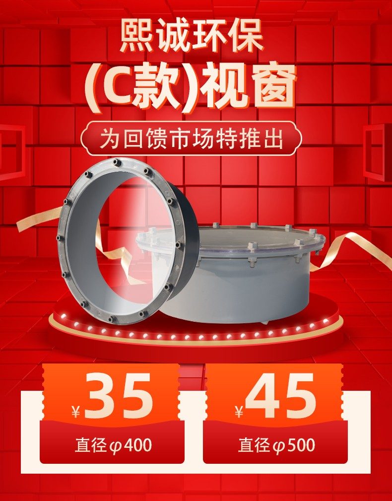
PP Equipment Window
| Product Model | Molded Manhole Viewing Port Series |
|---|---|
| Category | PP Molded Products |
| Reference Price | Price on request |
Product Overview
PP sight glass, also known as manhole sight glass or observation port, is a molded fitting with a transparent viewing panel installed on the side wall of corrosion-resistant equipment such as spray towers, washing towers, and activated carbon boxes. Through the viewing panel, operators can observe the uniformity of spray distribution, whether the packing is blocked, or if the demisting layer is carrying water without shutting down or opening the cover, enabling timely judgment of the internal condition of the equipment.
The sight glass mainly consists of a PP flange frame, a transparent viewing panel, a sealing gasket, and fastening screws. The flange frame is injection-molded and welded onto the open hole of the equipment cylinder. The transparent viewing panel is tightened and fixed with screws and a sealing gasket. When inspection or maintenance inside the tower is required, the panel can be removed as a small manhole. During daily operation, it serves as an observation port. The panel material is transparent and corrosion-resistant, capable of withstanding the acidic and alkaline mist environment inside the tower.
The molded sight glasses supplied by Xicheng Environmental Protection include screws and sealing gaskets. The opening sizes are standardized, and only welding is required at the predetermined positions on the cylinder at the site, making assembly convenient. The sight glasses are typically installed at corresponding positions on the cylinder for the spray layer, packing layer, and demisting layer, with one key location per layer, allowing operators to observe the equipment's operating condition section by section.
Working Principle
The observation function of the sight glass relies on the transparent viewing panel. The panel is made of transparent material with excellent light transmission and corrosion resistance. When installed on the side wall of the cylinder, it forms a visible window. Light from inside the tower passes through the panel, allowing operators to see the spray liquid distribution, liquid droplets carried by airflow, and the surface condition of the packing from the outside. Some sight glasses can be paired with internal lighting to improve observation in dim environments.
The sealing principle of the sight glass is similar to that of a flange. A corrosion-resistant sealing gasket is placed between the transparent viewing panel and the PP flange frame. After the surrounding screws are tightened evenly, the gasket deforms under pressure, filling the gaps between the mating surfaces and blocking the escape of tower gas. During tower operation, the internal environment is typically micro-negative or micro-positive pressure. Uniformly tightened flat sealing is sufficient to prevent gas leakage. When maintenance is needed, the screws can be loosened, and the panel can be removed to access the opening or insert tools.
Structural Composition
The sight glass consists of a flange base, a transparent viewing panel, a sealing gasket, a pressure frame, and fasteners. The flange base is a PP injection-molded frame, with the outer ring welded to the edge of the cylinder's open hole, and the inner ring forming the sealing surface and screw holes. The transparent viewing panel is embedded in the frame, surrounded by a sealing gasket on all sides. The pressure frame or screw washers press the edges of the viewing panel, and after the bolts are tightened, the panel and sealing gasket are fixed to the base.
The viewing panel is the core wear part of the sight glass. Long-term exposure to acidic and alkaline mist and ultraviolet light may cause it to age, yellow, or crack. The design allows for replaceable structure, where screws can be loosened to replace the panel and sealing gasket. The flange frame, after welding to the cylinder, is used for long-term service, while the panel and sealing gasket are replaced as maintenance spare parts. The opening of the sight glass comes in two forms: circular and square. Circular openings distribute stress evenly, while square openings provide a larger observation area.
Specification Model Table
The table below provides a description of the components and configuration of the sight glass. The opening sizes are matched to the equipment diameter.
| Component | Function | Maintenance |
|---|---|---|
| Flange Base | Welds to cylinder opening | Long-term use |
| Transparent Viewing Panel | Transmits light for internal observation | Replaceable |
| Sealing Gasket | Presses to prevent leaks | Regular replacement |
| Fasteners | Presses the viewing panel | Corrosion-resistant treatment |
Product Features
PP sight glass makes the internal state of enclosed towers visible, serving as a practical accessory for operation, inspection, and maintenance. The main features are as follows.
- Observes spray, packing, and demisting conditions without shutting down
- Injection-molded flange frame with sealing gasket for reliable sealing without gas leakage
- Viewing panel and sealing gasket are replaceable, with low maintenance costs
- Removable panel can serve as a small inspection port and sampling port
- Overall corrosion-resistant to acids and alkalis, suitable for tower mist environments
- Standard openings include screws and sealing gaskets for convenient on-site assembly
- Can be arranged in layers at spray, packing, and demisting sections
| Frame material | PP / PPs Polypropylene |
|---|---|
| Material of Vision Panel | Corrosion-resistant transparent material |
| Molding Process | Flange Frame Injection Molding |
| Sealing Method | Sealing Strip Flat Compression |
| Fixed mounting method | Bolt Fastening Our bolt fastening solutions are designed to meet the highest industry standards, ensuring precision and reliability in |
| Connected to the cylinder | Welding Our welding solutions are designed to meet the highest industrial standards, ensuring precision, durability, and efficiency in |
| Corrosion resistance performance | `Acid and Alkali Misting` |
| Function | Observation / Maintenance / Sampling |
| Spares | View panel gasket is replaceable |
| View Panel Features | High transparency for easy observation |
| Specifications Shape | Round / Square Option Available |
Application Industries
- Observation port for cylindrical body corresponding to the sprinkling layer of spray tower
- Inspection window for clogging condition of packing layer in washing tower
- Observation of liquid droplet entrainment at demister section
- Inspection port for activated carbon layer status in activated carbon adsorption box
- Operational observation of acid-alkali exhaust gas treatment tower in electroplating process
- Visual maintenance port for reaction section of chemical absorption tower
- Observation and sampling port for laboratory and small-scale exhaust gas equipment
Typical Process Locations
Viewports are welded onto key process sections of tower and box side walls. In spray towers, viewports are typically installed at each height of sprinkling pipes to observe nozzle misting and liquid film distribution; viewports are set above and below the packing section to check for scaling blockage or liquid deviation; demister section viewports are used to observe water carry-over at the outlet. The placement of viewports also considers operator standing height and inspection pathways for convenient daily observation.
During equipment maintenance, viewports serve as a transition between routine inspections and shutdown maintenance. In operation, viewports allow internal status assessment through the viewport plate, enabling abnormal findings to trigger planned shutdowns where the viewport plate is removed to insert inspection tools or serve as a small manhole for entry into the tower. Viewports cannot replace standard manholes for large-scale equipment; personnel entering the tower must still use standard manholes and comply with confined space work requirements. Before welding, precise hole positioning is marked on the cylindrical body, edges are polished smooth, and flange bases are welded coaxially to the cylinder with sealed welds. Viewport plates and sealing strips are assembled only after the cylinder cools and is cleaned to avoid thermal damage to transparent components. During operation, avoid impact or excessive pressure on the viewport plate; clean with soft cloths and neutral detergents, and regularly inspect for aging of sealing strips and scratches on the viewport plate, replacing it promptly upon detecting haziness or cracks.
Related Products
View More Hot
Hot
PVC Flexible Duct Connector
 Hot
Hot
PVC Plastic Damper
 Hot
Hot
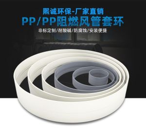
PP plastic ring
 Hot
Hot
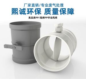
PP Manual Damper
Get Quote
PP Manual Damper / Molded Manhole Viewing Port Series