
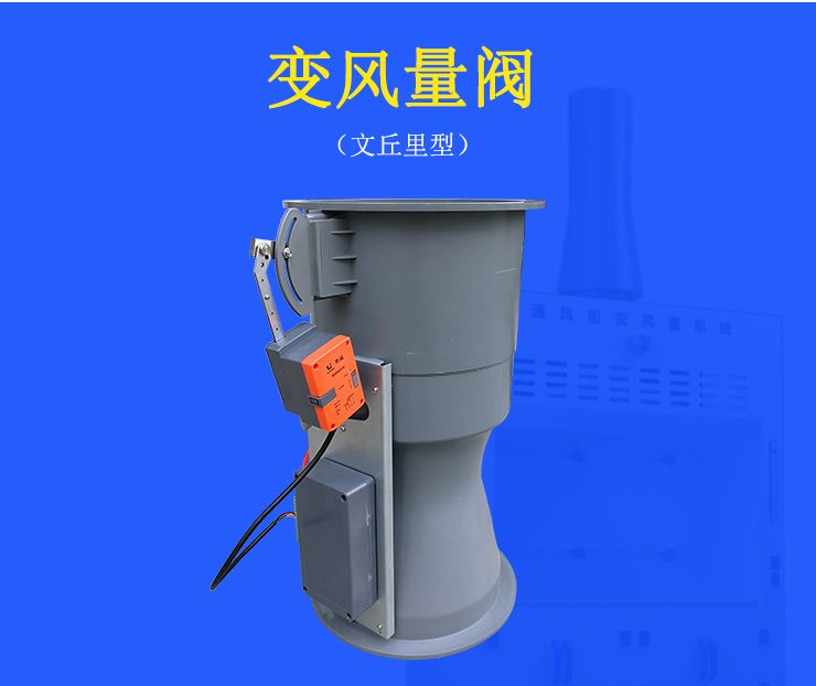
Variable Air Volume Venturi Valve
| Product Model | VAV Venturi Variable Air Volume Valve |
|---|---|
| Category | Laboratory Products |
| Reference Price | Price on request |
Product Overview
The Variable Air Volume (VAV) Venturi Valve,Abbreviation VAV Venturi Valve, is the core control device for laboratory variable air volume ventilation systems, installed on the exhaust branch pipe of fume hoods. It enhances the Venturi valve body with an airflow measurement section, a differential pressure sampling tube, a controller, and an electric actuator. The built-in measurement section detects the exhaust airflow in real time. The differential pressure signal is transmitted from the sampling tube to the controller's sensor. The control chip compares the measured airflow with the target airflow and commands the actuator to drive the valve core (blade) to rotate and change the opening degree, allowing the exhaust airflow to follow the fume hood sash opening, maintaining a constant sash face velocity.
When the fume hood sash is pushed up or down, the opening area changes continuously. In a constant airflow system, the exhaust airflow remains constant, resulting in higher face velocity and energy waste when the sash is closed, or potentially below safe levels when the sash is open. The VAV Venturi Valve automatically increases the exhaust airflow when the sash is opened and decreases it when the sash is closed, using a sash position sensor or a face velocity control mode, keeping the face velocity within a safe range. This ensures harmful gases are not released while significantly reducing exhaust airflow when the sash is closed, saving air conditioning fresh air and fan energy. It is the mainstream solution for modern laboratory ventilation control.
The VAV Venturi Valve body supplied by Xicheng Environmental Protection is made of fireproof and flame-retardant materials, corrosion-resistant, and suitable for acid and alkali exhaust environments. The controller supports displacement control and face velocity control modes, with airflow display, fault alarm, and building communication interface. The actuator responds quickly and adjusts stably, and can be integrated with variable frequency exhaust fans, fresh air systems, and laboratory monitoring systems to achieve intelligent and energy-efficient operation of fume hood exhaust.
Working Principle
The working process of the VAV Venturi Valve is a rapid closed-loop control. Airflow enters the valve and first passes through the built-in airflow measurement section. The measurement section utilizes Venturi throttling or multi-point velocity measurement to generate a differential pressure corresponding to the airflow. The sampling tube transmits the differential pressure signal to the differential pressure sensor on the controller. The chip calculates the real-time exhaust airflow based on the differential pressure. The controller also receives signals from the fume hood sash position sensor or face velocity setting to calculate the required target exhaust airflow for the current sash opening.
When the measured airflow differs from the target airflow, the control chip outputs a command to drive the electric actuator, which moves the valve core or adjusts the blade to change the valve's flow area: if the airflow is too high, it closes the valve; if too low, it opens it. This continues until the measured airflow returns to the target value. The entire measurement, comparison, and execution process rapidly cycles, allowing the airflow to follow the sash movement in a very short time while maintaining a constant face velocity. The Venturi valve body's flow channel characteristics ensure a stable relationship between the valve core opening and airflow, and strong resistance to network pressure fluctuations. The fireproof and flame-retardant valve body and corrosion-resistant measurement components ensure long-term contact with acid and alkali exhaust without corrosion or measurement drift, guaranteeing control accuracy and reliability.
Structural Components
The VAV Venturi Valve consists of a Venturi valve body, adjustable valve core or blade, airflow measurement section, differential pressure sampling tube, controller, electric actuator, and interfaces. The valve body is a cylindrical Venturi shape, made of fireproof and flame-retardant engineering materials, corrosion-resistant, with circular interfaces at both ends for connection to air ducts. The valve core inside is driven by the actuator to change the area of the annular flow channel.
The airflow measurement section is located in a stable airflow area inside the valve and is connected to the controller's differential pressure sensor via the sampling tube. The controller integrates a chip, display, buttons, and communication interface, installed on the valve body or nearby, receiving signals from the sash position sensor and face velocity sensor, and outputting actuator control commands. The electric actuator is directly installed on the valve shaft, with manual operation and position feedback. The system also includes a sash position sensor, face velocity sensor (for face velocity control mode), audible and visual alarm panel, and variable frequency fan linkage interface. Multiple VAV valves can be connected to the laboratory ventilation monitoring system via a communication bus.
Specification Model Table
The following table compares the control of VAV valves and CAV valves based on ventilation system type for selection.
| Item | VAV Valve | CAV Valve |
|---|---|---|
| Exhaust Airflow | Varies with sash opening | Constant |
| Face Velocity | Constant at any opening | Fixed opening qualified |
| Energy Consumption | Energy-saving when sash is closed | Full airflow operation |
| Configuration | Controller and actuator | Mechanical spring |
Product Features
The VAV Venturi Valve provides closed-loop air control, ensuring safety and energy efficiency, and is the core device for modern laboratory fume hood ventilation control. Its main features are as follows.
- Real-time airflow measurement and closed-loop adjustment, maintaining constant face velocity
- Automatic airflow reduction when sash is closed, significantly saving fresh air energy consumption
- Stable Venturi measurement, strong resistance to network pressure fluctuations
- Fast response, quickly following sash movement
- Fireproof and flame-retardant, corrosion-resistant valve body, suitable for acid and alkali exhaust environments
- Includes airflow display, fault alarm, and communication interface
- Can be integrated with variable frequency fans and building automation systems
| Body Material | Fireproof and Flame-Retardant Engineering Materials |
|---|---|
| Control Method | LCV Control |
| Measurement Components | Integrated airflow measurement section |
| Signal Transmission | Pressure Differential Sampling Tubing |
| Actuator | Electric actuator drives valve core |
| Control Mode | Displacement / Face Airflow Mode |
| Control Objective | Constant face air velocity |
| Corrosion resistance performance | Acid and Alkali Corrosion Resistance |
| Communication Interface | Optional Building Communication |
| Energy-saving Features | Window closure reduces airflow |
Application Industries
- VAV Control for Modern Chemical Laboratory Fume Hoods
- VAV Ventilation Systems for Pharmaceutical R&D and QC Laboratories
- Exhaust Control for Ventilation Cabinets in Wet etching Areas of Semiconductor and Panel Factories
- Energy-Saving Ventilation Renovation for Testing and Certification Laboratory Labs
- Centralized VFD Exhaust System for Ventilation Cabinets in University Research Buildings
- Safe Ventilation for Hospital Pathology and Disease Control Laboratories
- Laboratories with High Energy Consumption and Face Velocity Safety Requirements
Typical Process Locations
The VAV Venturi Valve is installed on the top of each VAV fume hood or on the exhaust branch pipe, positioned as close as possible to the fume hood exhaust outlet. Straight pipe sections are retained before and after the valve to ensure accurate measurement. Displacement sensors are installed on the viewing windows, and face velocity display and alarm devices are installed on the fume hood panels. Each VAV valve's exhaust branch pipe is connected to horizontal dry pipes and a central exhaust fan. The airflow demand of multiple valves is aggregated via a communication bus to coordinate the VFD operation of the exhaust fan, allowing the fan's airflow to vary with actual demand, achieving system-level energy savings. The fresh air system operates in VFD mode to maintain room pressure difference and supply air balance.
During installation, the valve body is installed according to the airflow direction markings. The sampling gas pipe connections are correct and airtight, actuators and controllers are wired properly, and sensor cables are routed to avoid strong electrical interference. In the commissioning phase, each valve's airflow is calibrated, and face velocity set points are set. The stability and response time of face velocity at fully open, half-open, and closed viewing window positions are tested. Multi-valve coordination and fan VFD joint commissioning are then performed to verify the emergency exhaust mode (fully open viewing window alarm). After commissioning, airflow measurement and sensors are regularly calibrated to ensure long-term reliable face velocity performance.
Related Products
View More
 Hot
Hot
Venturi Valve
 Hot
Hot
Ventilation Hood
 Hot
Hot
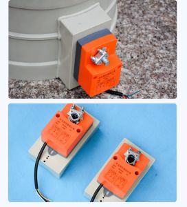
Switching Type Corrosion-Resistant Actuator
Get Quote
Switching Type Corrosion-Resistant Actuator / VAV Venturi Variable Air Volume Valve