

PP Formed Flange
| Product Model | Injection Molded Flat Weld Flange Series |
|---|---|
| Category | PP Molded Products |
| Reference Price | Price on request |
Product Overview
The PP Formed Flange is a disc-shaped pipe connection component molded by polypropylene injection molding, with evenly distributed bolt holes on the disc surface. When two flanges are brought together, bolts are inserted and tightened, and a sealing gasket is installed in the middle to achieve a secure connection between pipes and pipes or pipes and equipment. The flange connection exhibits excellent sealing performance and is easy to disassemble, making it the primary connection method in ventilation systems requiring maintenance and sectioning.
Compared to manually welded flanges, injection molded flanges offer higher dimensional accuracy, a smooth disc surface, and precisely positioned bolt holes, ensuring consistent batch quality. When connecting to air ducts, the pipe end is inserted into the flange neck socket and then fixed with a welding rod. The weld is located at the flange neck, leaving the sealing surface unaffected. The product is resistant to acid, alkali, and salt corrosion, does not rust, and is significantly lighter than metal flanges.
The PP Formed Flanges supplied by Xicheng Environmental Protection are compatible with the nominal diameter series of formed air ducts, available in a full range of specifications from smaller to larger diameters, and can also be provided in flame-retardant PP material. The flange sealing surface is flat, and when paired with rubber or PTFE gaskets, evenly tightened bolts can withstand positive and negative pressures in the ventilation system, making it suitable for connections between towers, fans, dampers, and pipes.
Working Principle
The flange connection relies on the pre-tightening force of the bolts to compress the gasket between the two flange sealing surfaces, achieving a seal. After the bolts are tightened, the gasket undergoes elastic deformation to fill the microscopic irregularities of the sealing surface, blocking the path for gas leakage along the joint. The flange distributes the concentrated force of the bolts evenly around the entire circumference, ensuring that the pipe joint maintains tight contact even when subjected to wind pressure and the weight of the pipes.
The corrosion resistance principle of the formed flange lies in its overall polypropylene material, which matches the material of the air ducts and equipment. The inner surface and sealing surface in contact with corrosive gases contain no metal. Although the connecting bolts are typically metal components, they are located outside the flange disc and do not directly contact the medium. Additional plastic bolt caps or corrosion-resistant treatment can be applied to adapt to corrosive environments. The weld and sealing surface work together to ensure the continuity of corrosion and sealing at the connection point.
Structural Composition
The formed flange consists of a flange disc, a neck socket, and bolt holes. The flange disc is a circular ring with a certain thickness, serving as the load-bearing area for bolt tightening and gasket sealing. The neck socket is designed to fit the outer diameter of the air duct and is welded in place after insertion. Bolt holes are evenly distributed around the disc circumference, with their diameter and number increasing with the diameter, ensuring uniform circumferential sealing pressure.
The flange sealing surface is fully flat and machined smoothly. On larger-diameter flanges, reinforcing ribs can be added to the back of the disc surface to enhance rigidity and prevent warping or deformation when bolts are tightened. The neck of the flange, where it is welded to the air duct, has sufficient length to ensure weld strength. Gaskets resistant to acid and alkali, PTFE gaskets, or other corrosion-resistant gaskets are selected based on the medium properties between the two flanges.
Specification and Model Table
The table below provides a structural and compatibility description of the formed flange, with specific dimensions corresponding to the air duct diameter series.
| Component | Function | Matching Parts |
|---|---|---|
| Flange Disc | Bolt Tightening and Sealing | Bolts and Nuts |
| Neck Socket | Air Duct Insertion and Welding | PP Welding Rod |
| Sealing Surface | Sealing with Gasket to Prevent Leakage | Corrosion-Resistant Gasket |
Product Features
The PP Formed Flange offers reliable connections and easy assembly, making it a standard connection component for corrosion-resistant ventilation pipes. Its main features are as follows.
- Injection molded in one piece, with a smooth disc surface and accurately positioned bolt holes
- Reliable flange connection sealing, capable of withstanding wind pressure in the ventilation system
- Easy to assemble and disassemble, facilitating equipment maintenance and pipe section cleaning
- Overall corrosion resistance to acid, alkali, and salt, without rust, and lightweight
- Compatible with formed air duct diameter series, with a full range of specifications for convenient selection
- Insertion welding fixation, with welds not affecting the sealing surface
- Available in flame-retardant material, meeting indoor fire safety requirements
| Material | PP / PPs Polypropylene |
|---|---|
| Molding Process | Integral injection molding |
| Connection Type | Flange Bolt Connection |
| Sealing Surface Form | Flat Panel Display Our flat panel displays are designed for high performance and reliability, meeting the needs of various |
| Fixed with ductwork | Splice Welding |
| Corrosion resistance performance | Acid-alkali-resistant |
| Companion Gaskets | Anti-corrosion gasket |
| Flame Retardant Options | PPs self-extinguishing |
| Pressure Rating | Low-voltage ventilation applicable |
| Matching Port | Multiple size options available |
| Bolt hole positions | Processed according to standards |
Application Industries
- Flange connections for inlet and outlet of spray towers and washing towers with air ducts
- Corrosion-resistant fan inlet and outlet connections with main ventilation pipelines
- Connections of electric and manual dampers at both ends of pipelines
- Interfaces for regularly maintained equipment such as activated carbon adsorption boxes
- Segmented disassembly and assembly exhaust pipelines in chemical workshops
- Connections of acid and alkali exhaust systems in semiconductor and electroplating production lines
- Connections of exhaust pipelines of laboratory fume hoods with main pipelines
Typical Process Locations
Formed flanges are installed at pipeline nodes requiring disassembly, maintenance, or equipment connections. Equipment inlet and outlet typically come with flanges. After welding formed flanges to the pipeline ends, they are aligned with equipment flanges, with gaskets added and tightened with bolts. Valves, silencers, and other pipeline components are also connected to the system via flanges for easy replacement later. Flanges are installed at regular intervals along straight pipeline sections for segmented installation and cleaning.
In exhaust treatment systems, flanges are concentrated at the inlet and outlet of towers, inlet and outlet of fans, both ends of dampers, and interfaces of adsorption equipment. During installation, ensure the two flanges are coaxial and parallel, with gaskets centered, and bolts tightened diagonally in stages for even distribution to avoid unbalanced stress causing flange warping and leaks. The quality of flange connections directly determines whether the system leaks under negative pressure. Before installation, verify nominal diameter, sealing surface type, and bolt hole distribution. When welding the spigot end to air ducts, maintain the flange surface perpendicular to the pipeline axis to prevent misalignment. Bolts should be tightened diagonally in two to three stages for even distribution, with gaskets centered and not reused. Protect the sealing surface from scratches during hoisting and handling. If flange leaks are detected during operation, first relieve pressure before evenly retightening or replacing gaskets.
Related Products
View More Hot
Hot
PVC Flexible Duct Connector
 Hot
Hot
PVC Plastic Damper
 Hot
Hot
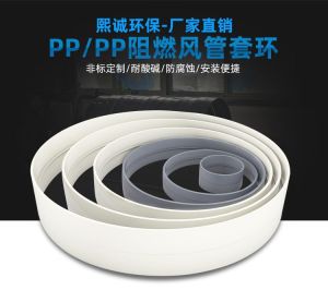
PP plastic ring
 Hot
Hot
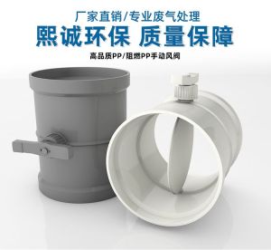
PP Manual Damper
Get Quote
PP Manual Damper / Injection Molded Flat Weld Flange Series