
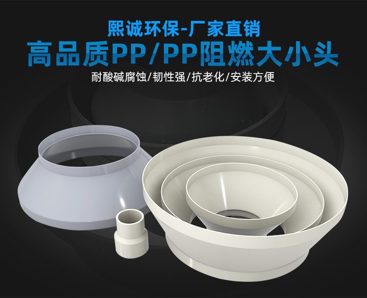
PP Size Head
| Product Model | Injection Molded Variable Diameter Series |
|---|---|
| Category | PP Molded Products |
| Reference Price | Price on request |
Product Overview
PP reducer, also known as a variable diameter pipe or eccentric fitting, is a transitional fitting used in ventilation duct systems to connect two pipes of different diameters. When the duct transitions from a larger to a smaller diameter, or when the inlet/outlet diameter of equipment does not match the duct diameter, the reducer ensures a smooth transition, avoiding eddies and increased air resistance caused by abrupt changes in duct cross-section.
The PP reducers supplied by Xicheng Environmental Protection are produced through injection molding in one piece, featuring seamless construction, no splicing, uniform wall thickness, and smooth inner surface. Made of polypropylene, they are available in standard PP and flame-retardant PP materials, resistant to acid, alkali, and salt corrosion, lightweight, and can be connected to formed ducts via slip-fit or flange methods for quick installation.
Reducers are categorized into concentric and eccentric types based on their shape. Concentric reducers have their two ends' centers aligned on the same straight line, suitable for vertical ducts and horizontally aligned ducts requiring high centering. Eccentric reducers have their two ends' centers not on the same axis, used for leveling the top or bottom of horizontal ducts to prevent liquid or gas accumulation at the diameter change point.
Working Principle
The working principle of reducers is to change the duct's flow cross-section through a conical transition section. As airflow enters from the larger end and flows along the conical inner wall to the smaller end, it gradually accelerates or decelerates. The continuously varying cross-section avoids localized eddies and pressure loss caused by sudden contraction. Compared to directly joining two flanges of different diameters, formed reducers provide smoother transitions, resulting in lower system operating noise and energy consumption.
In terms of corrosion resistance, the injection-molded PP reducers feature uniform material composition with no welds as corrosion weak points. Corrosive gases passing along the smooth inner wall do not contact metal, preventing rust. For slip-fit connections, matching PP welding rods or flange gaskets are used for sealing, maintaining corrosion continuity at the joint, making them suitable for acidic/alkaline waste gas and corrosive exhaust environments.
Structural Composition
Formed reducers consist of three parts: a large-end receiving socket, a conical transition section, and a small-end receiving socket, all injection-molded. The inner diameters of the two receiving sockets match the outer diameters of corresponding duct specifications, with the duct inserted and welded or secured with fasteners during connection. The conical transition section has uniform wall thickness, with the transition angle designed to balance structural strength and airflow smoothness.
Eccentric reducers, based on the concentric structure, shift the conical section to one side, keeping one end's outer edge flush. When used for leveling the top of horizontal ducts, they prevent gas accumulation at the top. When leveling the bottom, they prevent liquid accumulation at the bottom. The product's two ends can be designed as slip-fit sockets, flange edges, or butt-weld connections to accommodate different pipe connection methods.
Specification Model Table
The table below shows the specification representation and selection key points for reducers, with specific diameter combinations available in matching duct series.
| Type | Connection Method | Applicable Scenario |
|---|---|---|
| Concentric Reducer | Slip-fit / Flange | Vertical ducts, aligned ducts |
| Eccentric Reducer | Slip-fit / Flange | Horizontal duct leveling |
| Flame-retardant Reducer | Slip-fit / Flange | Indoor fire protection requirements |
Product Features
PP formed reducers feature a simple and reliable structure, serving as the standard solution for duct diameter changes. With smooth inner surface transitions and low airflow resistance, both concentric and eccentric types meet different installation needs for horizontal and vertical ducts, with specifications flexibly combinable based on upstream/downstream diameters. Key features include:
- Injection-molded in one piece, no welds, fully corrosion-resistant with no weak points
- Conical smooth transition, low air resistance, reduced eddies and noise
- Concentric and eccentric types, adaptable to different installation requirements
- Smooth inner surface prevents dust adhesion, corrosion-resistant and rust-free
- Lightweight, slip-fit connection for quick installation, low labor costs
- Specifications match formed duct series for easy selection
- Available in flame-retardant material to meet indoor fire protection requirements
| Material | PP / PPs Polypropylene |
|---|---|
| Molding Process | Integral injection molding |
| Type | Concentric / Eccentric |
| Connection Method | `Spigot / Flange` |
| Corrosion resistance performance | Acid-alkali-resistant salt |
| Flame Retardant Options | PPs self-extinguishing |
| Inner wall features | Smooth transition |
| Accompanying Pipes | PP Formed Ductwork |
| Section Type | Primarily circular |
| Function | Conic Transition Connector Our conic transition connectors are designed to seamlessly connect pipes of different diameters, ensuring |
| Specifications Range | Various bore combinations |
Application Industries
- Adaptation of ductwork and equipment interfaces in electroplating workshop ventilation systems
- Flow transition between fan inlets/exits and main pipelines in chemical enterprises
- Adaptation connection of acid/alkali exhaust branch pipes merging into main pipelines in semiconductor factories
- Size matching between ductwork and dampers in laboratory ventilation systems
- Non-circular connection between inlet/outlet of spray towers and ductwork
- Contraction and expansion of exhaust pipelines in metallurgical pickling lines
- Splicing and transition of different specifications of ductwork in environmental treatment projects
Typical Installation Locations
Reducer/adapters are installed at nodes where pipe diameters change, commonly found at fan inlets/exits, equipment interfaces, and branch pipes merging into main pipelines. Fan inlets/exits typically have smaller diameters than main ducts, and after expansion via reducers/adapters, they connect to the main pipelines, reducing outlet velocity and resistance. When branch pipes merge into main pipelines, eccentric reducers/adapters are used for alignment, ensuring horizontal pipes are flush at the bottom or top.
In waste gas treatment processes, reducers/adapters are located in transition sections between collecting branch pipes and main pipelines, main pipelines and purification equipment, and purification equipment and fans. When selecting, ensure the diameters of both ends of the reducer/adapter match upstream and downstream pipelines. For horizontal pipes, eccentric reducers/adapters are preferred, while concentric reducers/adapters are used for vertical pipes. After installation, ensure proper sealing and fastening. Before installation, verify the diameters of both ends, concentric or eccentric design, and flange standards. For horizontal pipes, determine the eccentric direction based on exhaust or liquid discharge requirements to avoid forming air or liquid pockets. After aligning the contraction section with upstream and downstream pipelines coaxially, tighten the connection. For spigot-and-socket connections, ensure the bonding surfaces are clean. Install independent support brackets near fans and pumps at contraction sections to prevent the weight and vibration of equipment from transferring to thin-walled sections.
Related Products
View More Hot
Hot
PVC Flexible Duct Connector
 Hot
Hot
PVC Plastic Damper
 Hot
Hot
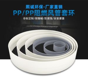
PP plastic ring
 Hot
Hot
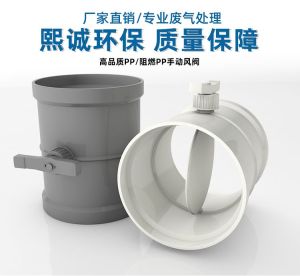
PP Manual Damper
Get Quote
PP Manual Damper / Injection Molded Variable Diameter Series