
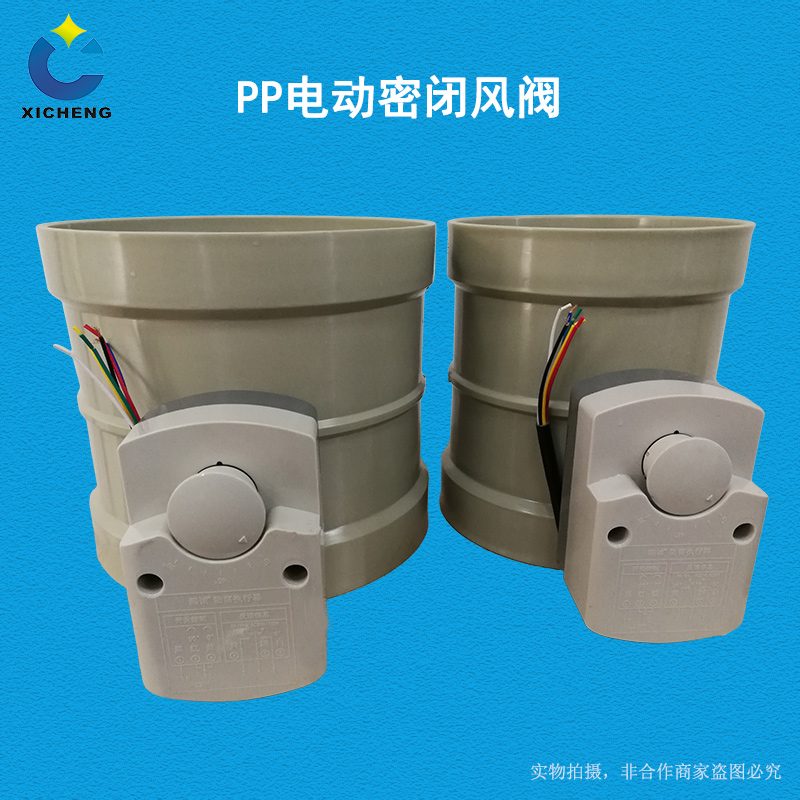
PP Electric Closed Damper
| Product Model | PP Electric Soft-Sealed Air Tight Valve |
|---|---|
| Category | PP Machined Products |
| Reference Price | Price on request |
Product Overview
The PP Electric Hermetic Damper is an electric corrosion-resistant damper designed for high air-tight closing. It resembles a conventional electric damper but features soft-seal structures on the vane edge and seat. The electric actuator provides sufficient clamping torque at the closed position, pressing the seal against the seat to reduce air leakage to a very low level. It primarily addresses the issue of conventional electric regulating valves still having noticeable gaps when fully closed, failing to reliably isolate gases.
In waste gas treatment systems, certain applications require the valve to truly cut off airflow after closure: isolating harmful gases during equipment shutdown and maintenance, preventing cross-contamination between standby and operating equipment, preventing corrosive gases or outdoor cold air from backflowing after fan shutdown, and preventing short circuits between parallel pipelines. Conventional dampers have gaps between the vane and body, allowing only regulation but not sealing. The Electric Hermetic Damper, with its soft-seal ring compression and electric actuator for remote automatic isolation, is the specialized valve for these applications.
The PP Electric Hermetic Dampers supplied by Xicheng Environmental Protection have PP or PPs corrosion-resistant bodies and are equipped with switching electric actuators and soft-seal vanes. They come with switch position signals and are available in circular, square, formed, and plate-welded large diameters. They can also be selected with a power-off reset actuator to meet emergency safety position requirements.
Working Principle
The air-tight principle of the hermetic damper is soft-seal compression. Corrosion-resistant elastic seals (such as rubber or flexible plastic strips) are embedded on the vane edge, and flat seats are set on the corresponding positions of the body. After the actuator drives the vane to the fully closed position, it continues to apply and maintain clamping force. The seal is compressed and deformed to fill the gap between the vane and seat, cutting off the gas passage with the elastic seal, resulting in significantly lower air leakage compared to conventional metal or plastic hard-contact dampers.
During opening, the actuator first detaches the vane from the seat before moving to the fully open position, avoiding prolonged friction on the seal. The electric control principle is the same as that of switching electric valves. The actuator receives switching signals to drive the valve shaft to rotate approximately 90 degrees. Limit switches control the fully open and fully closed positions and provide feedback signals. The PP body is resistant to acid and alkali corrosion, and the seals are selected to be compatible with waste gas components, corrosion-resistant and non-swelling. This is key to maintaining long-term air tightness of the hermetic valve.
Structural Components
The Electric Hermetic Damper consists of a body, a sealing vane, a shaft, a seat, an electric actuator, a bracket, and end connections. The body is a PP-formed cylindrical or plate-welded cylindrical structure with a flat seat ring at the fully closed position. The vane is a rigid plate with a sealing groove on the edge and embedded soft seals, fixed to the shaft, which is supported by a sealed shaft sleeve.
The shaft's extending end is installed with a switching electric actuator via a bracket. The actuator's output torque must exceed the clamping torque required for the seal and provide a margin. Some structures use a four-bar or cam mechanism to generate clamping action at the end of closure. The actuator includes full-open and full-closed limits and feedback, with optional spring reset. Square hermetic dampers use multi-leaf vanes, circumferential sealing strips, and leaf overlapping seals. The body connects at both ends via socket or flange, with reliable sealing at the shaft holes to prevent external leakage.
Specification Model Table
The table below shows the differences between hermetic dampers and conventional regulating dampers. Selection should be based on isolation requirements.
| Item | Electric Hermetic Valve | Conventional Electric Valve |
|---|---|---|
| Sealing | Soft ring compression | Hard contact gap |
| Full-closure air leakage | Very low | Higher |
| Application | Air-tight isolation | Regulation and actuation |
| Actuator | High-torque clamping | Standard torque |
Product Features
The PP Electric Hermetic Damper features soft-seal compression, low air leakage, and remote isolation, making it the specialized valve for harmful gas pipeline automatic isolation. Its main features are as follows.
- Soft-seal ring compresses the seat, resulting in low air leakage at full closure
- Electric actuator enables remote automatic isolation, eliminating the need for on-site operation
- Prevents backflow during shutdown, cross-contamination between equipment, and pipeline short circuits
- PP or PPs body, acid and alkali-resistant, flame-retardant
- Seals selected for compatibility with waste gas components, corrosion-resistant and non-swelling
- Includes switch position signals, suitable for interlock monitoring
- Available in circular, square, and various sizes, with optional power-off reset
| Body Material | PP / PPs |
|---|---|
| Sealing Form | Soft Seal Ring Compression |
| Drive Type | Electric Actuator |
| Control Type | Switching type |
| Fully Automatic Performance | Low Leakage Air Tight Seal Partition |
| Corrosion Resistance Performance | Acid and Alkali Salt Resistant |
| Sealing Selection | By Media Compatibility |
| Feedback Signal | Fully open and fully close in place |
| Connection Method | `Spigot / Flange` |
| Reset Options | Spring return optional |
Application Industries
- Isolation electric closed valves for maintenance of spray towers and adsorption equipment
- Windproof isolation between primary and backup fans and equipment
- Closed valves to prevent corrosive gas backflow after fan shutdown
- Isolation valves between hazardous gas pipelines and personnel areas
- Isolation valves to prevent short circuits between parallel exhaust gas treatment branches
- Air-tight isolation valves for laboratory ventilation system floor isolation
- Corrosive gas pipelines requiring automatic shutdown in emergency conditions
Typical Process Locations
The electric closed air valves are installed in positions requiring airtight isolation rather than airflow regulation: at the inlets and outlets of purification equipment (for equipment isolation during maintenance), connecting pipes between backup fans and backup equipment, fan outlets (to prevent backflow during shutdown), branch points of parallel pipelines, and where hazardous gas areas connect to other areas. The valves are interlocked with fans and equipment, opening during operation and automatically closing during shutdown or maintenance. In emergency conditions, they open or shut according to safety logic.
During installation, ensure the valve disc closing direction facilitates pressure-sealing using air pressure, and install the valve body according to the airflow indicators on the valve body. Both ends of the pipelines should have independent supports to prevent pipeline stress from deforming the valve seat and affecting the seal. The actuator is pre-wired for power supply, control, and feedback connections. During commissioning, focus on checking whether the sealing ring is evenly compressed in the fully closed position, whether the air leakage in the fully closed state meets requirements, and whether the power-off reset direction aligns with safety specifications.
Related Products
View More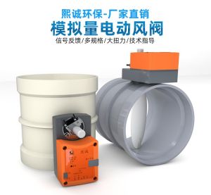 Hot
Hot
PP Fire-Resistant Analog Air Valve
 Hot
Hot
PP Fire-Resistant Closed-Check Valve
 Hot
Hot
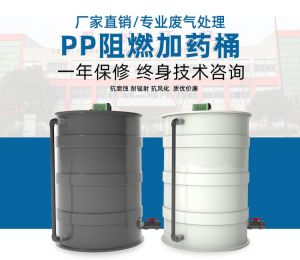
PP Flame Retardant Additive Drum
 Hot
Hot
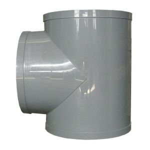
PP Flame Retardant Processed T-Connector
Get Quote
PP Flame Retardant Processed T-Connector / PP Electric Soft-Sealed Air Tight Valve