

PP Flame Retardant Processed Reducing Pipe
| Product Model | PPs plate-welded reducing elbow |
|---|---|
| Category | PP Machined Products |
| Reference Price | Price on request |
Product Overview
PP Flame-Retardant Miter Elbow, also known as reducing elbow or pipe reducer, is a conical transition piece used in ventilation ducts to connect two pipe sections of different diameters. Due to one end being larger and the other smaller, it is commonly referred to as a miter elbow. The miter elbow is formed by rolling and welding PP flame-retardant sheet material into a conical筒, with each end connected to large-diameter and small-diameter ducts or equipment, allowing the cross-sectional area of the pipe to change smoothly along the airflow direction.
In exhaust systems, as branch pipes merge or split, the main pipe diameter needs to change progressively. The diameters of fan inlets and outlets often differ from the duct diameters, requiring miter elbows at these junctions. Directly connecting pipes of different diameters creates abrupt expansions or contractions, resulting in significant local resistance, noise, and dust accumulation. Miter elbows smooth the change in cross-sectional area through their conical section, reducing the transition resistance to a lower level. Machined miter elbows are not limited by standard specifications and can be manufactured in any combination of diameters and lengths.
Miter elbows are available in concentric and eccentric types: concentric miter elbows have both ends aligned on the same axis, suitable for vertical pipes and general horizontal pipes; eccentric miter elbows have offset centers, with one side remaining flat, used in horizontal pipes where the top or bottom must remain level. Xicheng Environmental can machine PP flame-retardant miter elbows according to drawings, with optional flanges or spigot connections.
Working Principle
Miter elbows achieve smooth transitions between different diameters through a gradually varying cross-sectional area. When airflow moves from the larger end to the smaller end (converging), the velocity gradually increases while static pressure decreases; when moving from the smaller end to the larger end (diverging), the velocity decreases while static pressure rises. The conical transition allows the airflow to gradually accelerate or decelerate along the cone surface, avoiding vortices and flow separation caused by abrupt expansions or contractions, thereby reducing local pressure loss and alleviating airflow noise and erosion at the transition point.
Converging sections (small-in, large-out) are more prone to flow separation and vortices, so the cone angle of diverging miter elbows cannot be too large, and their length cannot be too short, requiring a sufficiently gradual expansion angle. The smooth inner surface of the PP sheet material facilitates airflow adherence, reducing flow separation. The material's corrosion resistance and flame-retardant properties ensure that the transition section remains rust-free in corrosive gases and self-extinguishes upon contact with fire. The continuous sealed welds along the cone prevent air leakage at the transition point.
Structural Composition
Miter elbows consist of a conical筒, longitudinal seams, and two end connection sections. The conical筒 is formed by rolling PP sheet material according to an unfolded pattern, with the longitudinal seams welded continuously using the same material electrodes. In concentric miter elbows, the cone surface contracts uniformly, while in eccentric miter elbows, the unfolded pattern has one side as a straight line and the other as a斜线. Flanges or spigots are welded to both ends for connection to the large-diameter and small-diameter pipes, respectively.
The large and small end flanges are drilled according to the corresponding pipe flange standards. Reinforcing rings are added to the cone wall based on the pipe diameter and negative pressure to prevent deformation of the large-end cross-section. The flat side of eccentric miter elbows is kept horizontal or vertically aligned during installation. Miter elbows can be used individually or often combined with flexible connectors, dampers, and fan inlet/outlet flanges to form variable-diameter connection assemblies.
Specification Model Table
The table below shows the types and applications of miter elbows, with both ends matching the corresponding pipes.
| Form | Characteristics | Application |
|---|---|---|
| Concentric Miter Elbow | Both ends coaxial | Vertical pipes and general horizontal pipes |
| Eccentric Miter Elbow | One side flat | Top or bottom must remain level |
| Converging / Diverging | Differentiated by flow direction | Branching, merging, and fan connections |
Product Features
PP Flame-Retardant Machined Miter Elbows feature smooth transitions and flexible specifications, making them essential variable-radius components for connecting different-diameter corrosion-resistant pipes. Key features include:
- PP sheet material rolled and welded, acid/alkali-resistant and self-extinguishing upon fire exposure
- Conical gradual cross-sectional area, reducing transition resistance and noise
- Both concentric and eccentric types, adaptable to different layouts
- Customizable for any diameter combination and length
- Smooth inner surface promotes airflow adherence, reducing flow separation and dust accumulation
- Flanges and spigots at both ends ensure reliable connection and sealing
- Same material welds as the duct, ensuring uniform system corrosion resistance
| Material | Flame Retardant PPS Sheets |
|---|---|
| Processing Technology | Rolling Cone Welding Our rolling cone welding technology ensures high precision and durability for industrial applications. Key Features: |
| Form | Concentric / Eccentric |
| Sectional Change | Contraction / Expansion |
| Connection Method | Flange / Spigot |
| Flame Retardancy | Self-extinguishing |
| Corrosion resistance performance | Acid and Alkali Resistant |
| Specifications and Features | Customized Non-Standard Port Combination |
| Strengthening Method | Variable Diameter Section Reinforcement Our Variable Diameter Section Reinforcement is designed to enhance structural integrity and |
| Inner wall features | Smooth transition |
| Applicable Section | Round / Rectangular |
Application Industries
- Branch ducts converging into main ducts at gradually reducing diameters
- Corrosion-resistant fans at inlet/outlet of ducts with different pipe diameters
- Variable diameter connecting sections for spray towers and purification equipment
- Offset reducing elbows for horizontal pipes requiring flat top alignment
- Transition from large-diameter main ducts to small-diameter branch ducts
- Connections between exhaust stacks and fan outlets with different pipe diameters
- Variable diameter sections at the junction of laboratory exhaust shafts and horizontal pipes
Typical Process Locations
Reducer elbows are installed at pipe diameter changes and equipment interfaces. In exhaust systems, airflow gradually converges from branch ducts to the main duct, which expands in diameter with increasing airflow volume, using gradually expanding reducers. When fan inlet/outlet diameters differ from duct diameters, flexible reducing connections are formed using reducer elbows with flexible joints. Reducing transitions are also required when equipment interface diameters differ from pipe diameters. Offset reducer elbows are commonly used on horizontal pipes to prevent liquid accumulation or maintain flat top alignment.
During installation, confirm the large and small ends based on airflow direction. The gradual expansion section should ensure a smooth expansion angle, and the flat side of offset reducer elbows should face the required alignment side. Flanges on both ends should be centered and tightened with gaskets for sealing. The reducer section and components like flexible joints and valves are supported by brackets. Flow velocity changes at reducer locations affect resistance and noise, so design should control flow velocities before and after reducers within reasonable ranges to avoid excessive expansion.
Related Products
View More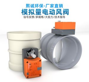 Hot
Hot
PP Fire-Resistant Analog Air Valve
 Hot
Hot
PP Fire-Resistant Closed-Check Valve
 Hot
Hot
PP Flame Retardant Additive Drum
 Hot
Hot
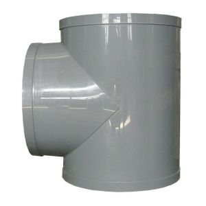
PP Flame Retardant Processed T-Connector
Get Quote
PP Flame Retardant Processed T-Connector / PPs plate-welded reducing elbow