
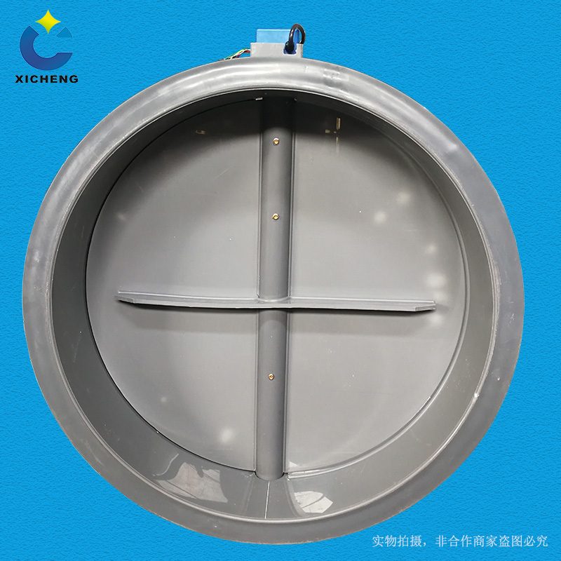
PP Fire-Retardant Process Electric Damper
| Product Model | PPs plate-welded round electric air valve |
|---|---|
| Category | PP Machined Products |
| Reference Price | Price on request |
Product Overview
The PP Flame-Retardant Processed Electric Air Damper is an automatic airflow switching valve equipped with an electric actuator, mounted on a circular valve body welded from PP Flame-Retardant plates. The valve body is formed by rolling and welding PP Flame-Retardant plates, and the vane is driven to rotate by the electric actuator outside the valve through the valve shaft. Operators send switch signals from the control cabinet or upper computer, and after the actuator is powered on, it drives the vane to rotate between fully open and fully closed positions, achieving remote start/stop and automatic isolation of the air duct without manual on-site operation.
In automated exhaust systems, equipment start/stop, workshop zoning exhaust, maintenance isolation, and emergency ventilation interlock all require automatic valve switching. Electric dampers are linked with fans and purification equipment: when the fan starts, the valve automatically opens, and when it stops, the valve automatically closes to prevent gas backflow and loss of hot/cold air after shutdown; in emergency conditions, emergency dampers can be opened or relevant branch lines can be closed based on signals. The PP Flame-Retardant valve body self-extinguishes upon fire exposure and is acid/alkali-resistant, making it suitable for corrosive exhaust systems in indoor and fire-rated environments.
The flame-retardant electric air dampers processed by Xicheng Environmental Protection have a circular plate-welded structure, with non-standardized diameters and wall thicknesses, and are equipped with switching-type electric actuators, featuring full-open/full-close position feedback signals. They can also be selected with a manual reset mechanism for manual operation during power outages. Actuator protection level and torque are selected based on installation environment and vane torque.
Working Principle
The electric air damper is powered by an electric actuator. The motor in the switching-type actuator drives the output shaft to rotate approximately 90 degrees via a reduction gear, connecting the output shaft to the valve shaft of the air damper to drive the vane to rotate from fully closed to fully open or vice versa. After reaching the set position, the internal limit switch cuts off the motor power and holds the position, while simultaneously outputting a passive contact signal to indicate the valve's open/close status. A control circuit provides an open/close electrical signal to complete the action.
The corrosion-resistant and flame-retardant properties of the valve body are ensured by PP plates and matching welding electrodes, preventing rust and jamming of the vane in corrosive gases, and the material self-extinguishes without propagating flames upon fire exposure. The electric actuator is installed outside the valve body, not in contact with corrosive gases. Seals and bearings are provided at the valve shaft exit through the valve body to prevent corrosive gas leakage along the shaft while ensuring smooth shaft rotation. The actuator is connected to the plastic valve shaft via a bracket and coupling, with actuator torque matched to the vane's air-driven torque to avoid motor overload caused by an underpowered drive.
Structural Components
The electric air damper consists of a PP plate-welded valve body, vane, valve shaft, shaft seat seal, electric actuator, installation bracket, and flanges. The valve body structure is the same as that of flame-retardant processed manual air dampers, with reinforced vanes for large diameters. The difference lies in one end of the valve shaft extending from the valve body and connecting to the output shaft of the electric actuator via a coupling, supported by a metal bracket fixed to the valve body or pipeline.
The electric actuator includes a motor, reduction mechanism, limit switch, position feedback, and manual operation mechanism, with an outer casing protection level suitable for the installation environment. The valve body ends are PP flanges or socket connections, and the vane edges can be equipped with sealing strips to enhance closing air tightness. Control cables are connected to the actuator junction box, with switching-type actuators typically featuring power, open valve control, close valve control, and full-open/full-close feedback terminals. Large-diameter valves are selected with high-torque actuators or models equipped with reset springs.
Specification and Model Table
The following table outlines the differences in control types and functions of electric air dampers, which must be clarified during selection.
| Type | Operation | Typical Application |
|---|---|---|
| Switching-Type | Full Open/Full Close | Remote Start/Stop and Isolation |
| Analog-Type | Any Position | Continuous Airflow Regulation |
| Reset-Type | Power Failure Return | Emergency Safety Position |
Product Features
The PP Flame-Retardant Processed Electric Air Damper can be remotely automatically started/stopped and interlocked with equipment, serving as a key valve for automated corrosive exhaust systems. Its main features are as follows.
- PP plate-welded valve body, self-extinguishing and acid/alkali-resistant
- Electric actuator-driven, remote switching without on-site presence
- Interlocked with fans and purification equipment to prevent backflow and cross-contamination
- Features full-open/full-close position feedback for status monitoring
- Large-diameter vanes reinforced, actuator torque matched
- Optional power failure reset and manual operation for emergency convenience
- Non-standard diameters and wall thicknesses, customized for flame-retardant air ducts
| Body Material | PPs Flame Retardant Panels |
|---|---|
| Processing Technology | Roll Forming and Welding Assembly |
| Section Shape | Round |
| Drive Type | Electric Actuator |
| Control Type | Switching Full On/Full Off |
| Feedback Signal | Fully open and fully close in place |
| Flame Retardancy | Self-extinguishing |
| Corrosion resistance performance | Acid and Alkali Resistant Salt |
| Connection Method | Flange / Spigot |
| Emergency Operation | Manual reset optional |
Application Industries
- Exhaust ventilation for automated plating production lines with equipment start-stop control
- Remote isolation valves for zoned exhaust systems in chemical workshops
- Electric dampers with fan inlet/outlet interlock
- Floor-level electric switch valves for centralized laboratory exhaust systems
- Electric valves with signal-driven operation for emergency ventilation systems
- Automatic isolation air duct valves for purification equipment maintenance
- Corrosion-resistant electric exhaust dampers for unattended server rooms and pipe galleries
Typical Process Locations
Electric dampers are installed on circular PPs ducts requiring automatic operation or remote isolation, typically at fan inlets/outlets, equipment exhaust connections, zoned branch pipes, and emergency ventilation lines. When fan interlock is enabled, electric dampers are linked to the fan control circuit: valves open before fans start, and fans stop before valves close to prevent load-starting and gas backflow. Power supply, control cables, and maintenance space are reserved near actuators; actuators of high-mounted valves are oriented for easy maintenance.
In control systems, on/off electric dampers connect to digital output ports of PLCs or ventilation control cabinets, while position signals link to digital inputs. Valve status is displayed on supervisory interfaces. In systems with shared fans, branch dampers for inactive equipment close to save air volume. During commissioning, valve diaphragm movement is manually verified locally before remote linkage and position signal verification.
Related Products
View More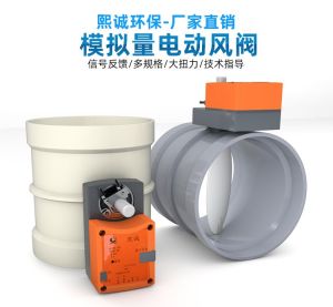 Hot
Hot
PP Fire-Resistant Analog Air Valve
 Hot
Hot
PP Fire-Resistant Closed-Check Valve
 Hot
Hot
PP Flame Retardant Additive Drum
 Hot
Hot
PP Flame Retardant Processed T-Connector
Get Quote
PP Flame Retardant Processed T-Connector / PPs plate-welded round electric air valve