
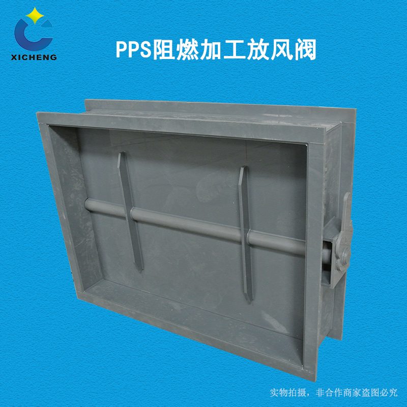
PP fireproofing processed square valve
| Product Model | PPs plate-welded rectangular multi-leaf damper |
|---|---|
| Category | PP Machined Products |
| Reference Price | Price on request |
Product Overview
The PP Flame-Retardant Square Air Damper is a square fireproof and corrosion-resistant air volume regulating damper with multiple linkage vanes, featuring a rectangular valve body formed by folding and welding PP flame-retardant plates, and integrated with multiple linkage vanes. It upgrades the valve body, vanes, and welding rods to all flame-retardant PP materials based on the PP processing square air damper, offering acid/alkali corrosion resistance and self-extinguishing properties. It is primarily used for laboratory fume hood exhaust, indoor ceiling rectangular ducts, and corrosion-resistant exhaust systems in fire-requiring areas.
Rectangular ducts in laboratory and factory ceilings are numerous and widely distributed, often located in enclosed spaces. If the duct material is flammable, fires can easily spread through the ceiling ducts and are difficult to detect. The PP Flame-Retardant Square Air Damper, when paired with flame-retardant rectangular ducts, forms a complete flame-retardant and corrosion-resistant exhaust network. The multi-vane Interconnection (linking) damper is used for air volume balancing in each fume hood and branch duct. The rectangular multi-vane structure features uniform opening and rigid vanes, making it suitable for applications requiring precise face velocity balancing, such as fume hood exhaust.
Xicheng Environmental can fabricate PP Flame-Retardant Square Air Dampers based on the cross-sectional dimensions of rectangular ducts. The number of vanes is configured according to the valve height. The square flange is matched with PP square pipes, and sealing strips can be added to the edges and ends of the vanes. The handle includes an opening lock, and it can also be equipped with electric or analog actuators to meet variable air volume control for fume hoods.
Working Principle
The adjustment principle of the flame-retardant square air damper is multi-vane Interconnection (linking). Turning the handle or actuator drives the main valve shaft, which, through a crank and connecting rod mechanism, synchronously drives all valve shafts, causing multiple vanes to rotate at the same angle. This changes the multiple airflow gaps of the rectangular cross-section, continuously regulating the air volume. When the vanes are closed, their edges overlap to seal the airflow path, and when open, they align parallel to the airflow. The synchronous movement of multiple narrow vanes ensures uniform cross-sectional opening and consistent air velocity at all points.
The flame-retardant principle is the same as that of circular PP air dampers. The valve body, vanes, welding rods, and sealing components are all flame-retardant or hard-to-burn materials, self-extinguishing and not propagating flames, ensuring the fire integrity of rectangular duct systems in ceilings and indoor spaces. In terms of corrosion resistance, PP vanes do not rust or warp when long-term exposed to laboratory acid/alkali fumes, and the Interconnection (linking) pins are made of corrosion-resistant materials, ensuring long-term synchronous and flexible operation of the multi-vane mechanism in corrosive environments. The outer wall of the rectangular valve body features reinforced ribs to resist negative pressure and prevent large panels from concaving.
Structural Composition
The flame-retardant square air damper consists of a PP rectangular valve body, multiple vanes, valve shafts, crank and connecting rod Interconnection (linking) mechanism, handle or actuator, and square flange. The valve body is formed by folding and welding four PP plates into a square frame, with longitudinal and corner seams continuously welded using PP flame-retardant welding rods, and reinforced ribs welded to the outer wall. The vanes are narrow and long PP plates, each fixed to a valve shaft and arranged parallel along the valve height.
Each valve shaft extends from the same side of the valve body and is equipped with a crank. A vertical connecting rod links them synchronously. The main valve shaft is connected to a handle, opening disc, and locking mechanism, or directly installed with an electric actuator. Sealing strips made of corrosion-resistant and flame-retardant materials can be embedded at the edges and ends of the vanes. When closed, the vanes overlap and fit against the side walls to minimize air leakage. The two ends of the square PP flange correspond to the Flange hole position (flange hole positions) of rectangular ducts. For larger cross-sectional valves, the vanes are reinforced at the edges, and the Interconnection (linking) connecting rods are located within a removable cover for easy maintenance.
Specification Model Table
The table below shows the driving modes and applicable scenarios of the flame-retardant square air damper, with cross-sectional dimensions matching rectangular ducts.
| Driving Mode | Control Characteristics | Applicable Scenario |
|---|---|---|
| Manual Multi-Vane | Adjustment Lock | Constant Air Volume Branch |
| Electric On/Off | Remote Operation | Branch Ducts Requiring Isolation |
| Analog Electric | Continuous Adjustment | Variable Air Volume Fume Hoods |
Product Features
The PP Flame-Retardant Square Air Damper is corrosion-resistant, flame-retardant, and features multi-vane uniform airflow distribution, making it a specialized valve for laboratory and ceiling rectangular exhaust systems. Its main features are as follows.
- PP plates folded and welded into a rectangular valve body, self-extinguishing and acid/alkali resistant
- Full flame-retardant welding rods for valve body and vanes, ensuring safety for ceiling use
- Multi-vane Interconnection (linking) with connecting rods for synchronized operation, uniform opening, and precise air volume balancing
- Narrow vanes with high rigidity, stable under high air pressure
- Sealing strips added to vane edges for minimal leakage when closed
- Square flange matched with PP square pipes, available in non-standard dimensions
- Compatible with switch-type or analog actuators, suitable for VAV systems
| Body Material | PPs Flame Retardant Panels |
|---|---|
| Welding Rod Material | PPs Flame-Retardant Welding Rod |
| Processing Technology | Sheet metal welding assembly |
| Section Shape | rect |
| Leaflet Valve Form | Multi-leaf linkage |
| Flame Retardant Properties | Self-extinguishing |
| Corrosion Resistance Performance | Acid-alkali-resistant salt |
| Connection method | Square Flange |
| Drive Options | Manual / Electric / Analog |
| Sealing Options | Leaflet edge soft seal |
| Sheet Thickness | Select by cross-section |
Application Industries
- Flame-retardant rectangular air damper for fume hood exhaust in chemical laboratory
- Drop ceiling multi-leaf regulating damper for laboratory exhaust in teaching and research
- Corrosion-resistant rectangular exhaust damper for indoor semiconductor and panel factory
- PPs square duct valve for ceiling-mounted exhaust in plating workshop
- Corrosion-resistant exhaust dry pipe valve for hospital laboratory and pathology
- Rectangular corrosion-resistant branch line isolation damper in fire-rated compartment
- Analog regulating damper for variable air volume fume hood system
Typical Installation Locations
Flame-retardant square damper is installed on PPs rectangular ducts in indoor and ceiling spaces. One damper is set on each fume hood exhaust port or floor-level horizontal branch/dry pipe in the ventilation system to balance exhaust airflow of each hood and maintain face velocity. A branch line isolation damper is installed before the floor or fire-rated compartment connects to the vertical shaft. When the damper is integrated into the ceiling or duct shaft, maintenance openings must be reserved on the side of the operating handle and linkage mechanism. For electric valves, power supply and control lines must also be reserved.
In constant air volume systems, manual multi-leaf dampers are adjusted and locked once. In variable air volume fume hood systems, analog electric flame-retardant square dampers are installed on the fume hood top or branch pipes, driven by the ventilation system face velocity controller to continuously regulate the damper vane. Rectangular ducts passing through fire-rated compartments require separate fire dampers and seals according to fire protection design. Flame-retardant square dampers cannot replace fire protection dampers. During installation, square flanges must be centered, gaskets sealed, and the valve shaft installed horizontally to ensure even vane weight distribution.
Related Products
View More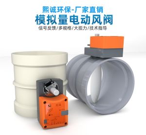 Hot
Hot
PP Fire-Resistant Analog Air Valve
 Hot
Hot
PP Fire-Resistant Closed-Check Valve
 Hot
Hot
PP Flame Retardant Additive Drum
 Hot
Hot
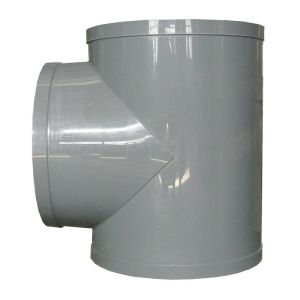
PP Flame Retardant Processed T-Connector
Get Quote
PP Flame Retardant Processed T-Connector / PPs plate-welded rectangular multi-leaf damper