
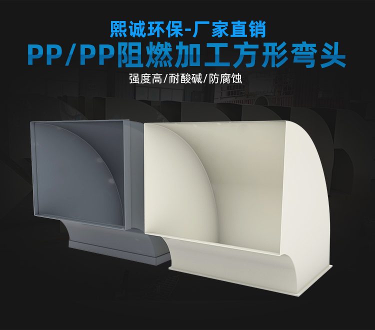
PP Flame Retardant Processed Elbow
| Product Model | PPs plate-welded rectangular elbow |
|---|---|
| Category | PP Machined Products |
| Reference Price | Price on request |
Product Overview
The PP fire-retardant fabricated square elbow is a plate-welded fitting used to change the direction of rectangular ventilation ducts. It is made from PP fire-retardant plates, cut according to the elbow layout, bent, and welded together. The ends of the square elbow are square flanges, which connect to the rectangular ducts. Based on the direction of turn, they are classified as horizontal elbows or vertical elbows, with common angles being 90 degrees, but other angles such as 45 degrees can also be processed.
Elbows are areas where local resistance is concentrated in exhaust ducts. When airflow changes direction at an elbow, it generates eddies and pressure loss. Fabricated square elbows can be equipped with internal flow guide vanes to smoothly direct airflow, significantly reducing local resistance and noise, which is particularly important for large-capacity rectangular ducts. The PP material is acid and alkali-resistant, self-extinguishing, and matches the material of the square ducts, ensuring uniform corrosion and fire protection performance of the entire system after welding.
Xicheng Environmental can customize fire-retardant fabricated square elbows based on the cross-sectional dimensions of the rectangular ducts, the turning angle, and installation space. The curvature radius of the elbow, flange type, and number of flow guide vanes can be designed according to requirements. They are compatible with square ducts, square tees, and square-to-round transitions, making them suitable for turning sections of rectangular ducts in laboratories, electroplating workshops, and factory mezzanines.
Working Principle
The function of the square elbow is to change the direction of airflow. After entering the elbow, the airflow turns 90 degrees or other angles along an arched or angled channel and exits. During the turning process, the outer wall guides the airflow, while the inner wall forms a low-speed eddy zone. Elbows with flow guide vanes use multiple arched vanes to divide the duct into several parallel flow paths, allowing the airflow to turn in layers, reducing eddy zones and secondary flow, thereby lowering the local resistance coefficient, reducing fan energy consumption, and minimizing elbow noise.
The corrosion and fire-retardant properties of the square elbow are guaranteed by the PP plates and matching welds. Corrosive exhaust gases exert stronger scouring force on the outer wall during turning. The PP material does not react with acids or alkalis, so the outer wall and flow guide vanes remain corrosion-resistant even under continuous airflow scouring. The fire-retardant components ensure self-extinguishing when exposed to fire, and the indoor rectangular duct system does not propagate flames when passing through ceilings or floors, just like straight ducts. Welds run continuously along the plate joints, preventing air leakage at turning points.
Structural Composition
The square elbow consists of two side wall plates, inner and outer curved plates (or folded plates), end square flanges, and optional flow guide vanes, all welded together. The side wall plates are cut according to the elbow angle and curvature, and the inner and outer side plates are bent or joined to form the turning channel. Longitudinal seams at the corners and circumferential seams are continuously welded. The two end flanges are matched with the flanges of the rectangular ducts, with bolt holes aligned.
Flow guide vanes are arched PP plates fixed at equal intervals between the side walls. Large-capacity elbows are equipped with multiple vanes, while small-capacity elbows may not have them. The outer wall of the elbow is reinforced with ribs based on negative pressure and size, with additional triangular reinforcements near the flanges. Horizontal and vertical elbows have the same structure, differing only in the plane where the airflow turns after installation.
Specification and Model Table
The table below shows the classification and configuration of square elbows, with cross-sectional dimensions matching rectangular ducts.
| Classification | Turning Direction | Configuration |
|---|---|---|
| Horizontal Elbow | Horizontal Plane Turning | Optional Flow Guide Vanes |
| Vertical Elbow | Vertical Turning | Optional Flow Guide Vanes |
| Angle | 90 Degrees / 45 Degrees | Custom Made |
Product Features
The PP fire-retardant fabricated square elbow offers smooth turning and flexible dimensions, making it a matching turning component for rectangular corrosion-resistant ducts. Key features include:
- PP plates bent and welded, acid and alkali-resistant with self-extinguishing properties
- Available in horizontal and vertical angles, custom-made on-site
- Internal flow guide vanes reduce turning resistance and noise
- End square flanges for easy connection to rectangular ducts
- Matching welds with square ducts ensure uniform system corrosion and fire protection performance
- Outer wall ribs maintain cross-sectional stability under negative pressure
- Compatible with square tees and square-to-round transitions for complete network connections
| Material | PPs Flame Retardant Boards |
|---|---|
| Processing Technology | Panel splicing |
| Section Shape | Rectangle |
| Elbow Angle | 90 degree / 45 degree customizable |
| Steering Form | Horizontal bending / Vertical bending |
| Guide Vane Our guide vanes are designed for optimal fluid flow management in industrial | Optional Configuration |
| Connection Method | Square Flange |
| Flame Retardancy | Self-extinguishing |
| Corrosion resistance performance | Acid and Alkali Resistant Salt |
| Strengthening Method | Back Reinforcement Rib for Elbow |
| Plate Thickness | Select by cross-section |
Application Industries
- Rectangular duct elbows for laboratory fume hood exhaust
- Horizontal turning of wall-mounted rectangular ducts in electroplating workshops
- Up-and-down bending of wide flat ducts in factory ceilings
- Square duct elbows for exhaust in semiconductor factory interlayers
- Elbows for connecting vertical shafts to horizontal square ducts
- Corrosion-resistant ducts requiring small-radius turns in confined spaces
- Rectangular ducts with flow guides for high airflow turning sections
Typical Installation Locations
Square elbows are installed at nodes where rectangular ducts change direction, commonly found at pipe corner turns along walls, intersections between vertical and horizontal pipes, and bending points to avoid beams, columns, and equipment. Horizontal elbows are used for horizontal turns, while vertical elbows are used for vertical bends. The flanges at both ends of the elbow connect to the square duct. Elbows near fan inlets/outlets and high-flow sections are preferably equipped with flow guide vanes.
During installation, ensure the elbow orientation aligns with airflow direction. Flange gaskets must be sealed, and bolts tightened evenly. The elbows and connected fittings are supported by hangers; flanges should not bear the weight of the pipes or flow guide vanes. Small-radius elbows have high resistance, so where space permits, larger radius elbows or those with flow guide vanes should be prioritized to reduce system resistance and operating noise.
Before installing square elbows, verify cross-sectional dimensions, turning angles, and horizontal/vertical orientation. For elbows with flow guide vanes, note the airflow direction markings. Flanges must be centered and tightened before securing the hangers. The back of the elbow and flow guide vanes are prone to wear and dust accumulation. Hangers should be positioned near the elbow's center of gravity. During operation, inspect flow guide vane fastenings and wall dust accumulation. In negative pressure systems, promptly reinforce and weld leaks if suction collapse or air leakage is detected.
Related Products
View More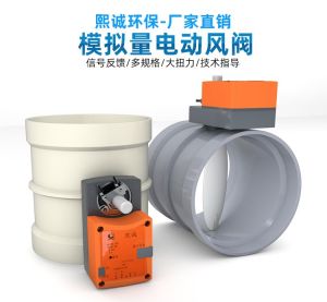 Hot
Hot
PP Fire-Resistant Analog Air Valve
 Hot
Hot
PP Fire-Resistant Closed-Check Valve
 Hot
Hot
PP Flame Retardant Additive Drum
 Hot
Hot
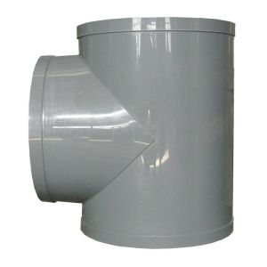
PP Flame Retardant Processed T-Connector
Get Quote
PP Flame Retardant Processed T-Connector / PPs plate-welded rectangular elbow